
Method for operating exhaust gas sensor

A technology of exhaust gas sensor and sensor element, which is applied in the testing of machines/structural components, instruments, electrical control, etc., and can solve the problem of damage to sensor elements

Pending Publication Date: 2022-06-03
ROBERT BOSCH GMBH
View PDF0 Cites 0 Cited by
  • Summary
  • Abstract
  • Description
  • Claims
  • Application Information

AI Technical Summary

Problems solved by technology

[0003] However, in the past there were occasional damaged sensor elements during operation of the exhaust gas sensor in the exhaust system of the vehicle

Method used


Image

  • Method for operating exhaust gas sensor
  • Method for operating exhaust gas sensor
  • Method for operating exhaust gas sensor

Examples


Embodiment Construction

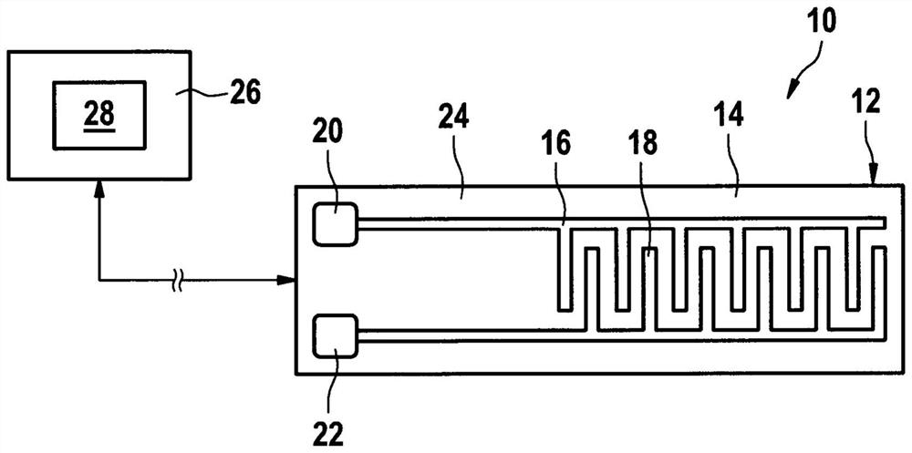
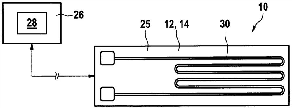
[0026] Figure 1a top view of the particle sensor 10 for probing and measuring particles in a gas according to one embodiment of the present invention. Particle sensor 10 is particularly configured to detect the air flow of the internal combustion engine, such as carbon black particles in the exhaust gas stream and for installation in the exhaust gas system of the vehicle. For example, the particle sensor 10 is configured as a carbon black sensor and can be arranged downstream of the carbon black particle filter of the vehicle having a diesel internal combustion engine. In the example shown, the measuring gas is the exhaust gas of the vehicle's internal combustion engine.

[0027] Particle sensor 10 includes a sensor element 12. The sensor element 12 includes a substrate 14. The substrate 14 is made of ceramic material, for example. The substrate 14 is basically squarely constructed. The sensor element 12 further comprises a first electrode 16, a second electrode 18, a first input...


PUM


Abstract

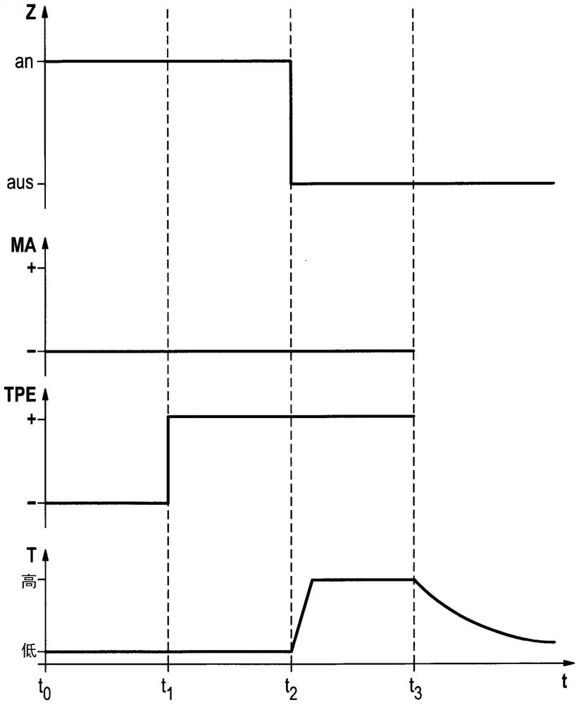
The invention relates to a method for operating an exhaust gas sensor in an exhaust gas system of an internal combustion engine of a vehicle, the exhaust gas sensor (10) having a ceramic sensor element (12) with at least one measuring electrode (16, 18) and a heating device (30), a binary end-of-dew signal (TPE) being calculated on the basis of data relating to the internal combustion engine and the exhaust gas sensor, the signal indicates whether the presence of liquid water can also be desired in the exhaust gas system, characterized in that the dew point end signal (TPE) is switched off only when the vehicle is switched off and the dew point end signal (TPE) has a value indicating that the presence of liquid water can still be desired in the exhaust gas system, and the dew point end signal (TPE) is switched off only when the vehicle is switched off and simultaneously the dew point end signal (TPE) has a value indicating that liquid water can still be desired. The sensor element (12) is heated to a temperature (T) by means of the heating device (30) thereof for a period of time in such a way that the sensor element (12) is dried.

Description

Background [0001] Known by the prior art a method of exhaust gas sensor in an exhaust gas device for running an internal combustion engine of a vehicle, wherein the exhaust gas sensor having a ceramic sensor element, the ceramic sensor element having at least one measuring electrode and heating device, wherein, based on data involving an internal combustion engine and an exhaust gas sensor is calculated a binary dew point end signal, which indicates: in the exhaust gas device is expected to still appear liquid water or is expected not to appear again. [0002] With the help of this signal, it is possible to avoid very intense heating of the ceramic sensor element for as long as liquid water is still expected in the exhaust gas unit. Thus, the so-called thermal shock of the ceramic sensor element, which can damage the ceramic sensor element, can be avoided. [0003] However, in the past, damaged sensor elements were occasionally found when the exhaust gas sensors in the vehicle's e...

Claims


Application Information

Patent Timeline
Patent Type & Authority Applications(China)
IPC IPC(8): F02D41/14F02D41/04
CPCF02D41/1446F02D41/1466F02D41/1438F02D41/042F02D41/1494F02D2041/1472G01M15/102G01N37/00
Inventor D·韦尔克F·京特M·马克斯M·蒂勒M·克伦克M·贝森
Owner ROBERT BOSCH GMBH
Learn More