Positioning clamp and machining method for rotor cover of dynamic pressure air bearing of gyro motor

A technology for positioning fixtures and rotor covers, applied in positioning devices, metal processing equipment, metal processing machinery parts, etc., can solve problems such as concave spherical surface crushing, unreasonable design of positioning fixtures, scratches, etc.

Active Publication Date: 2022-06-07
XIAN AEROSPACE PRECISION ELECTROMECHANICAL INST
View PDF9 Cites 2 Cited by
  • Summary
  • Abstract
  • Description
  • Claims
  • Application Information

AI Technical Summary

Problems solved by technology

[0009] In order to solve the unreasonable design of the positioning fixture for the precision machining of the rotor cover of the existing gyro motor dynamic pressure air bearing rotor, poor positioning accuracy, long alignment time during the process, low processing efficiency, and unreasonable cooperation between the concave spherical surface of the rotor cover and the positioning surface of the fixture caused the rotor The invention provides a positioning fixture and processing method for the rotor cover of the dynamic pressure air bearing rotor of a gyro motor to solve problems such as crushing and scratching of the concave spherical surface caused by the relative rotation of the cover and the spherical positioning mandrel.

Method used


Image

  • Positioning clamp and machining method for rotor cover of dynamic pressure air bearing of gyro motor
  • Positioning clamp and machining method for rotor cover of dynamic pressure air bearing of gyro motor
  • Positioning clamp and machining method for rotor cover of dynamic pressure air bearing of gyro motor

Examples


Embodiment Construction

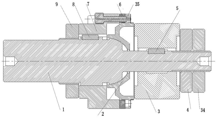
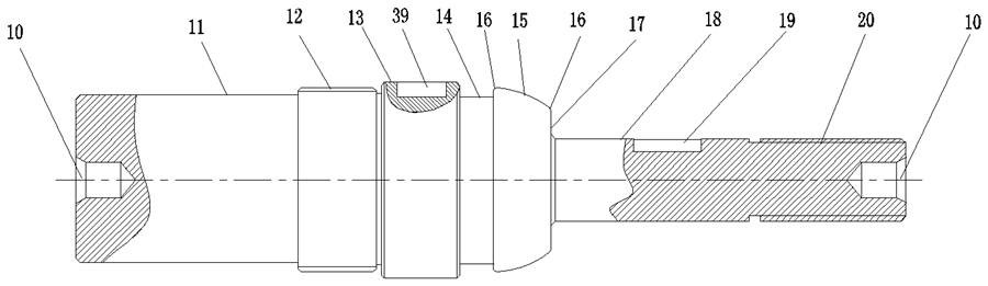
[0063] see Figure 2 to Figure 7 , Gyro motor dynamic pressure air bearing rotor cover positioning fixture, including spherical positioning mandrel 1, positioning collar 3, second flat key 5, compression nut 4, anti-loosening nut 34, vibration damping pad 6, positioning pin 35, back To the support seat 7, the first flat key 8 and the lock nut 9; the spherical positioning mandrel 1 is a coaxially arranged step shape, including a clamping section 11, a large thread section 12, a second guide cylinder section 13, a first Four keyway 39, ring groove section 14, spherical positioning section 15, ball table end surface 17, first guide cylindrical section 18, first keyway 19 and small thread section 20; high-precision top holes are machined at both ends of spherical positioning mandrel 1 10. It is used to adopt the positioning method of two tops on the machine tool; the clamping section 11 is used to install the fork to drive the rotation of the spherical positioning mandrel 1 throug...


PUM

PropertyMeasurementUnit
sphericityaaaaaaaaaa
surface roughnessaaaaaaaaaa
Circularityaaaaaaaaaa

Abstract

The invention relates to a thin-wall part precision turning machining method and a positioning clamp, in particular to a positioning clamp and a machining method of a gyroscope motor dynamic pressure air bearing rotor cover. The positioning clamp comprises a spherical surface positioning mandrel, a positioning lantern ring, an anti-vibration pad and a back supporting seat. The spherical positioning mandrel is a step shaft with center holes formed in the two end faces, and comprises a clamping section, a large thread section, a second guide cylindrical section, a spherical positioning section, a spherical table end face, a first guide cylindrical section and a small thread section from left to right in sequence. The machining method comprises the steps of first-step machining of the rotor cover, machining of a series of spherical positioning mandrels, machining of a positioning lantern ring and a back supporting seat, selection of a proper spherical positioning mandrel, turning of the rotor cover and the like. The problems that an existing machining method is poor in positioning precision and low in machining efficiency, and the concave spherical surface is crushed are solved, damage to the concave spherical surface is avoided by limiting six degrees of freedom, and the machining precision of the rotor cover is guaranteed.

Description

technical field [0001] The invention relates to a precision turning positioning fixture and a processing method for a rotor cover of a gyro motor dynamic pressure air bearing, in particular to a precision turning and positioning fixture for a thin-walled part with a stepped stopper outer circle and a high-precision concave spherical surface reversely distributed and with high coaxiality requirements. Turning positioning fixture and processing method. Background technique [0002] Three-floating gyroscope and two-floating gyroscope are small electromechanical gyroscopes with high precision and long life. They are mainly used in inertial navigation and guidance fields such as space stations, satellites, and spacecraft. "heart", which plays a vital role in the performance and lifespan of the three-floating gyro. In the gyro motor, the dynamic pressure air bearing is the key structural component. The dynamic pressure effect of the gyro motor through the high-speed rotation of 3...

Claims


Application Information

Patent Timeline
Patent Type & Authority Applications(China)
IPC IPC(8): B23Q3/00B23Q3/14B23P15/00
CPCB23Q3/00B23Q3/14B23P15/003B23Q2703/10
Inventor 邵荔宁柳亚楠胥鹏周光陈雨沼尹栋王鹏宇谢东伟
Owner XIAN AEROSPACE PRECISION ELECTROMECHANICAL INST
Why Eureka
Try Eureka