Explosion-proof and dust-proof ventilation equipment for underground engineering

A technology for ventilation equipment and underground engineering, applied in dust prevention, mining equipment, ventilation of mines/tunnels, etc., can solve problems such as gas explosions and polluted equipment, and achieve the effects of avoiding gas explosions, reducing concentration, and reducing wind speed

Pending Publication Date: 2022-06-07
冼志华
View PDF0 Cites 1 Cited by
  • Summary
  • Abstract
  • Description
  • Claims
  • Application Information

AI Technical Summary

Problems solved by technology

[0004] In order to overcome the gas concentration in the underground air, the concentration in the ventilation duct will gradually increase. When the gas explosion concentration limit is reached, there will be a danger of gas explosion, and the dust in the underground air will not be treated in time after settling, which will pollute the equipment. The shortcoming of this invention provides a kind of explosion-proof and dust-proof ventilating equipment for underground engineering

Method used


Image

  • Explosion-proof and dust-proof ventilation equipment for underground engineering
  • Explosion-proof and dust-proof ventilation equipment for underground engineering
  • Explosion-proof and dust-proof ventilation equipment for underground engineering

Examples


Embodiment 1

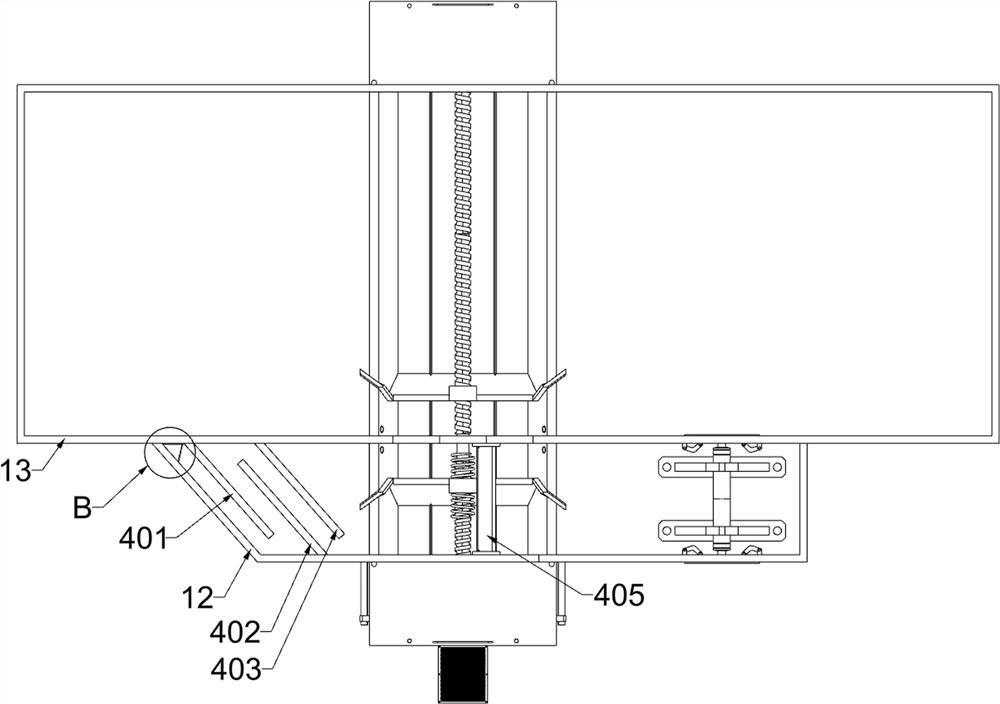
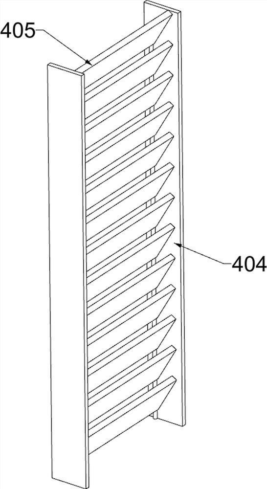
[0040] An explosion-proof and dust-proof ventilation equipment for underground engineering, such as Figure 1-14 As shown, it includes a ventilation pipe body 1, a transfer pipe 2, a fan 3, a sprinkler 4, a combustion unit, a dust removal unit and a flow velocity slowing unit; the upper side of the ventilation pipe body 1 is provided with a top cover plate 11; the top cover plate 11 The front part of the lower side is fixedly connected with the side expansion plate 12; the rear part of the lower side of the top cover plate 11 is fixedly connected with the pipe body plate 13; the rear side of the side expansion plate 12 is fixedly connected with the pipe body plate 13; The transfer pipe 2; the right side of the transfer pipe 2 is connected with the fan 3; the sprinkler 4 is installed on the lower side of the top cover plate 11; The lower side of the side expansion plate 12 is connected with the dust removal unit; the side expansion plate 12 and the tube body plate 13 are connec...

Embodiment 2

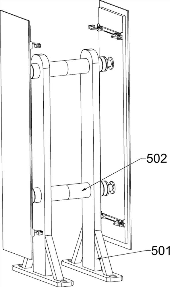
[0054] On the basis of Example 1, as figure 1 and Figure 15-17As shown, it also includes an air supply unit; the side expansion plate 12 is connected with an air supply unit; the tube body plate 13 is connected with the air supply unit; the air supply unit includes a mounting seat 501, a two-way electric push rod 502, a ventilation The door 503, the sliding rod 504, the sliding block 505, the second spring 506 and the connecting turning plate 507; two mounting seats 501 are fixedly connected to the right part of the inner and lower side of the side expansion plate 12; Two-way electric push rod 502; the upper part of the two mounting bases 501 is fixedly connected with another two-way electric push rod 502; the front telescopic ends of the two two-way electric push rods 502 are fixedly connected with a ventilation door 503; two two-way electric push rods The rear telescopic end of 502 is fixedly connected with another ventilation door 503; the opposite sides of the two ventil...


PUM


Abstract

The invention relates to the field of underground engineering, in particular to explosion-proof and dust-proof ventilation equipment for underground engineering. The technical problems that the concentration of gas in underground air in a ventilation pipeline can be gradually increased, when the concentration reaches a gas explosion concentration limit value, the danger of gas explosion exists, and dust in the underground air can pollute equipment due to the fact that the dust is not treated in time after settling are solved. According to the technical scheme, the explosion-proof and dust-proof ventilation equipment for the underground engineering comprises an adapter pipe, a fan and the like; the right side of the adapter communicates with a fan. Air with gas is intermittently injected into the closed space, and then the gas is ignited, so that the concentration of the gas in the underground air is reduced, and a large amount of gas cannot be ignited; and after the dust is sprayed and settled, the dust settles again in turbid liquid, so that the dust is accumulated and collected, and manual removal is facilitated.

Description

technical field [0001] The invention relates to the field of underground engineering, in particular to an explosion-proof and dust-proof ventilation device for underground engineering. Background technique [0002] In the prior art, the ventilation of the underground project is only the exchange of air. When the underground air is pumped into the ventilation duct by the fan, the gas concentration in the underground air will gradually increase in the ventilation duct. When the gas explosion concentration is reached. When the limit value is reached, there is a danger of gas explosion, and the underground air contains a large amount of dust, which directly discharges and pollutes the outside air, and directly sprays and settles. If it is not cleaned in time, it will also pollute the ventilation equipment and reduce the service life of the ventilation equipment. , and when the gas concentration suddenly rises to the gas explosion concentration limit, there is no ability to quick...

Claims


Application Information

Patent Timeline
Patent Type & Authority Applications(China)
IPC IPC(8): E21F1/00E21F1/08E21F5/04E21F7/00
CPCE21F1/00E21F1/08E21F5/04E21F7/00Y02B10/40
Inventor 冼志华
Owner 冼志华
Why Eureka
Try Eureka