Novel mining air cooler
An air cooler, mining technology, used in mining equipment, mine/tunnel ventilation, sustainable construction and other directions, can solve the problems of heavy weight, large dust content, large volume of air coolers, etc., to achieve easy installation and transportation, internal Compact structure and small volume effect
- Summary
- Abstract
- Description
- Claims
- Application Information
AI Technical Summary
Problems solved by technology
Method used
Image
Examples
Embodiment 1
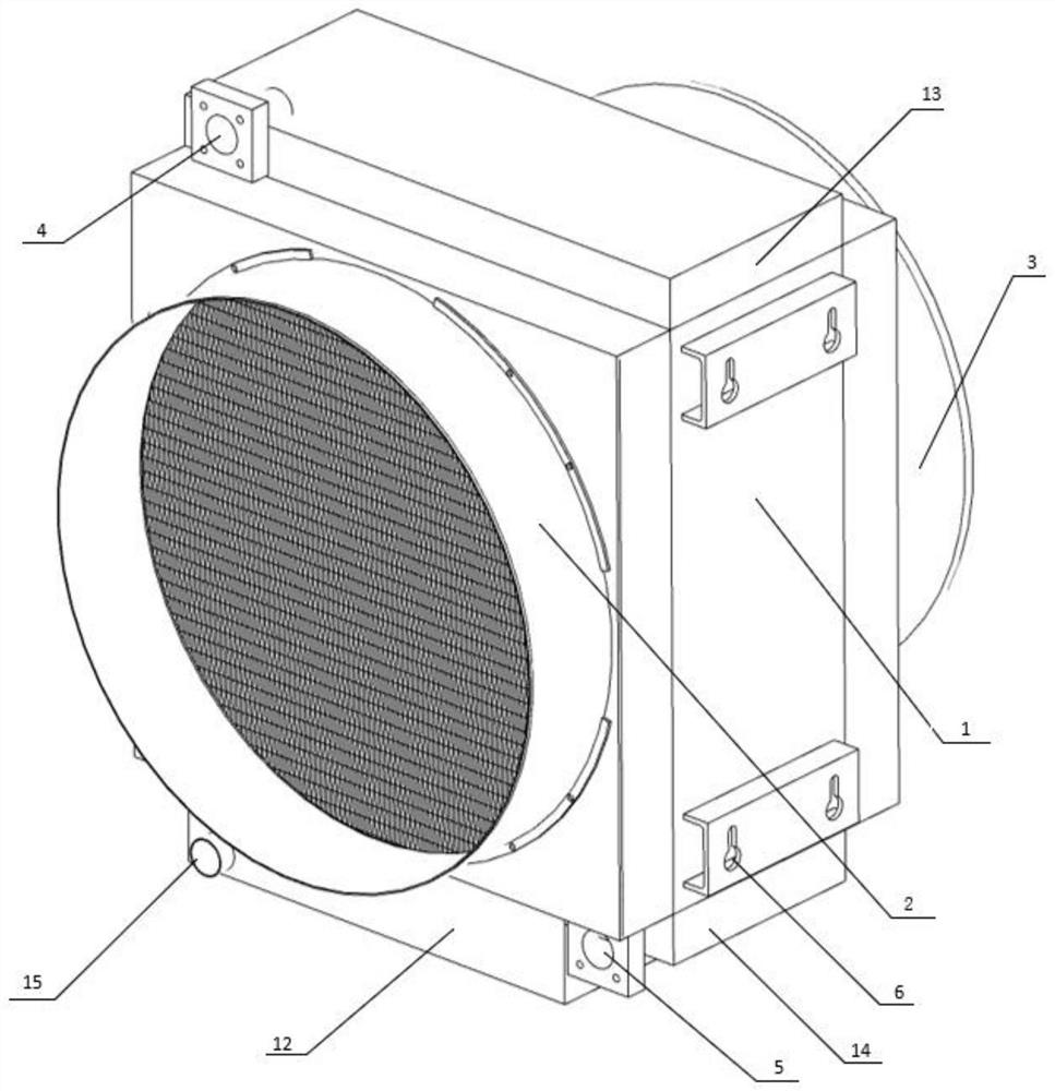
[0030] Reference Figure 1- Figure 3 As shown, the new mining air cooler of the present embodiment, comprising:
[0031] Chassis 1, the chassis 1 is provided with a cavity inside, the chassis 1 is provided with an air inlet 2 and an air outlet 3 that communicates with the cavity, and an inlet pipe 4 and an outlet pipe 5 in communication with the cavity, the chassis 1 is also provided with a lifting plate 6, the lifting plate 6 is provided on the lifting plate 6.
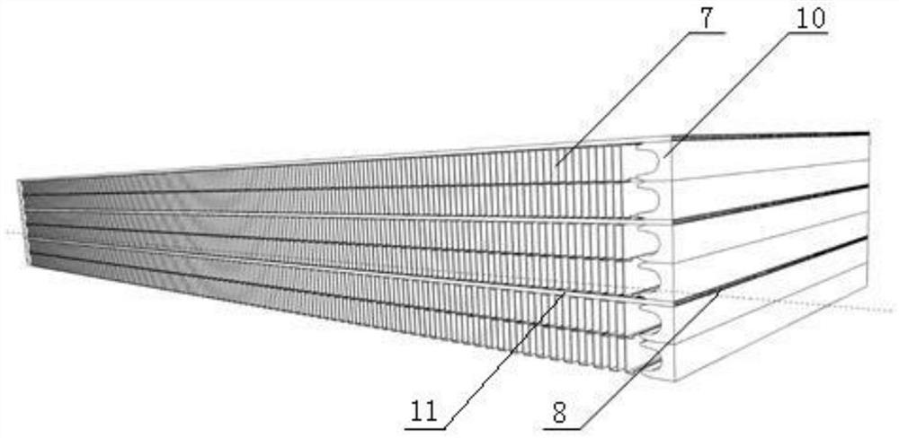
[0032] Duct fin 7, disposed in the cavity, the air duct fin 7 is communicated with the air inlet 2 and the air outlet 3, respectively, forming an air inlet channel 701, the air inlet channel 701 is connected with the fan outlet, and the air is introduced into the air inlet channel 701 by an external fan;
[0033]Aqueduct fin 8, disposed in the cavity, the waterway fin 8 is communicated with the inlet pipe 4 and the outlet pipe 5, respectively, to form an inlet channel 801;
[0034] Wherein, in the cavity, the air duct fin...
Embodiment 2
[0042] Reference Figure 1-Figure 5 As shown, the new mining air cooler of the present embodiment, comprising:
[0043] Chassis 1, the chassis 1 is provided with a cavity inside, the chassis 1 is provided with an air inlet 2 and an air outlet 3 communicated with the cavity, and the inlet pipe 4 and the outlet pipe 5 communicated with the cavity, the chassis 1 is also provided with a lifting plate 6, the hoisting plate 6 is provided on the hoisting plate 6;
[0044] Duct fin 7, disposed in the cavity, the duct fin 7 is communicated with the air inlet 2 and the air outlet 3, respectively, forming an air inlet channel 701, the air inlet channel 701 is connected to the air outlet of the fan;
[0045] Waterway fin 8, disposed in the cavity, the frozen water channel is communicated with the inlet pipe 4 and the outlet pipe 5, respectively, to form an inlet channel 801;
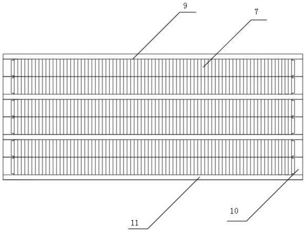
[0046] Wherein, in the cavity, the air duct fin 7 and the waterway fin 8 layered alternating arrangement, the air duct...
Embodiment 3
[0050] Reference Figure 6 As shown, the new mining air cooler of the present embodiment, comprising:
[0051] Chassis 1, the chassis 1 is provided with a cavity inside, the chassis 1 is provided with an air inlet 2 and an air outlet 3 communicated with the cavity, and the inlet pipe 4 and the outlet pipe 5 communicated with the cavity, the chassis 1 is also provided with a lifting plate 6, the hoisting plate 6 is provided on the hoisting plate 6;
[0052] Duct fin 7, disposed in the cavity, the duct fin 7 is communicated with the air inlet 2 and the air outlet 3, respectively, to form an air inlet channel 701, the air inlet channel 701 is connected with the fan outlet;
[0053] Aqueduct fin 8, disposed in the cavity, the waterway fin 8 is communicated with the inlet pipe 4 and the outlet pipe 5, respectively, to form an inlet channel 801;
[0054] Wherein, in the cavity, the air duct fin 7 and the waterway fin 8 layered alternating arrangement, the air duct fin 7 and the waterway ...
PUM
 Abstract
Description
Claims
Application Information
 - R&D
- Intellectual Property
- Life Sciences
- Materials
- Tech Scout
- Unparalleled Data Quality
- Higher Quality Content
- 60% Fewer Hallucinations
Browse by: Latest US Patents, China's latest patents, Technical Efficacy Thesaurus, Application Domain, Technology Topic, Popular Technical Reports.
© 2025 PatSnap. All rights reserved.Legal|Privacy policy|Modern Slavery Act Transparency Statement|Sitemap|About US| Contact US: help@patsnap.com


