Composite axle tube connected with metal joint

A technology of metal joints and composite materials, which is applied in the field of composite materials, can solve the problems of reduced strength of composite material shaft tubes, damage to composite shaft tube fiber continuity, complex processes, etc., and achieves the effect of good process versatility

Active Publication Date: 2022-06-07
江苏集萃碳纤维及复合材料应用技术研究院有限公司
View PDF10 Cites 1 Cited by
  • Summary
  • Abstract
  • Description
  • Claims
  • Application Information

AI Technical Summary

Problems solved by technology

Under this scheme, the shaft tube of composite material is guaranteed by the shape of foam tube and metal flange, and there are the following problems: this scheme is suitable for composite materials formed by filament winding, and other technological schemes cannot be used to form composite materials; The thermal expansion coefficient of composite materials does not match, which easily leads to deformation and inaccurate shape control
This method has the following problems: the internal and external threads are only suitable for wet winding, and there is a risk of difficult demoulding; the connection between the inner liner and the structural layer and the thermal expansion coefficient affect the shape accuracy of the composite shaft tube
However, both of these two methods require processing of the composite material shaft tube itself. Both of these methods damage the fiber continuity of the composite material shaft tube, resulting in a decrease in the strength of the composite material shaft tube itself.

Method used


Image

  • Composite axle tube connected with metal joint
  • Composite axle tube connected with metal joint
  • Composite axle tube connected with metal joint

Examples


Embodiment Construction

[0035]The present invention is not limited to the following specific embodiments, those of ordinary skill in the art can implement the present invention by using other various specific embodiments according to the content disclosed in the present invention, or use the design structure and thinking of the present invention, make simple changes or Modifications fall within the protection scope of the present invention. It should be noted that the embodiments of the present invention and the features of the embodiments may be combined with each other under the condition of no conflict.

[0036] The present invention is described in further detail below in conjunction with embodiment:

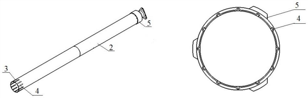
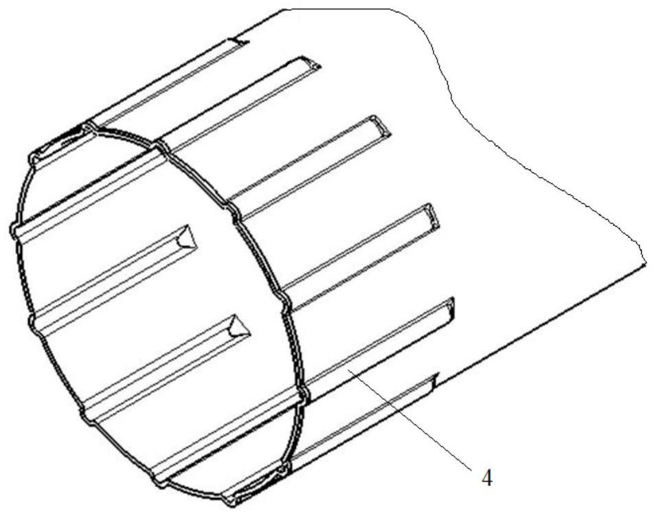
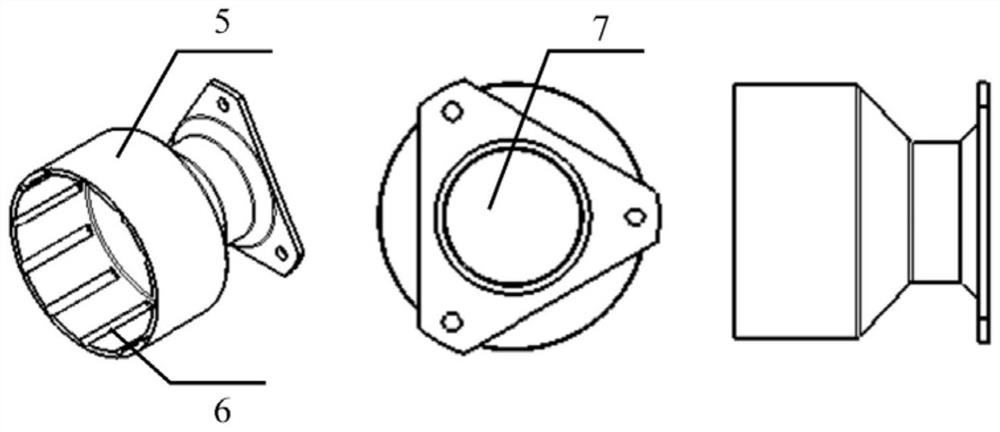
[0037] See Figure 1 to Figure 5 , the composite material shaft tube connected with the metal joint 5 in this embodiment includes the shaft tube body 1 and the metal joints 5 respectively connected and arranged at both ends of the shaft tube body 1 (the material of the metal joint 5 in this embodi...


PUM

PropertyMeasurementUnit
torqueaaaaaaaaaa

Abstract

The invention relates to the technical field of composite materials, in particular to a composite material shaft tube connected with a metal connector, which comprises a shaft tube body and the metal connector, the shaft tube body comprises a non-matching area located in the middle and matching areas integrally formed at the two axial ends of the non-matching area, and a plurality of salient points or bosses are uniformly arranged on the outer surfaces of the matching areas around the circumferential direction; the number of the convex points or the bosses in each matching area is not less than 3, if the convex points are designed, at least one row of convex points are distributed in the axial direction, the number n of the convex points or the bosses meets the formula, and r is the outer radius of the non-matching area of the shaft tube body; l is the length of the boss in the axial direction or the total length of a row of salient points distributed in the axial direction in the axial direction; alpha is the maximum angle, except 90 degrees, in the laying layer angles; the metal connector is provided with a recess matched with the boss or the salient point, the metal connector is in clearance fit with the matching area, and a glue film is arranged on the peripheral face of the matching area in advance. The composite material axle tube can transmit enough torque (at least 1800 N.m).

Description

technical field [0001] The invention relates to the technical field of composite materials, in particular to a composite material shaft tube connected with a metal joint. Background technique [0002] Drive shafts are widely used in various fields such as construction machinery, wind power generation, locomotives, marine propulsion devices and aerospace. With the development of the times, various industries have put forward higher and higher requirements for drive shafts, such as reducing weight, improving corrosion resistance, maintenance-free and noise reduction. Due to its high specific strength, high specific stiffness, and good corrosion resistance, composite materials are gradually being used in transmission shafts. [0003] At present, the composite material transmission shaft mainly comprises a composite material shaft tube and a metal joint arranged at both ends of the shaft tube connected. Typical connection methods include adhesive bonding, mechanical connection...

Claims


Application Information

Patent Timeline
Patent Type & Authority Applications(China)
IPC IPC(8): F16C3/02F16D1/068F16D1/076B29C70/30B29C70/54B29L23/00
CPCF16C3/02F16C3/026F16D1/068F16D1/076B29C70/30B29C70/54F16D2001/103F16D2250/00F16D2250/0069B29L2023/22Y02P70/50
Inventor 吴晓春邓嘉庚朱桂龙穆举杰
Owner 江苏集萃碳纤维及复合材料应用技术研究院有限公司
Why Eureka
Try Eureka