Solar heat cabinet

A solar thermal cabinet and heat collection technology, applied in the field of solar thermal cabinets, can solve the problems of inability to guarantee indoor heating demand in low temperature seasons, insufficient to ensure indoor heating in low temperature seasons, etc., and achieve the effects of compact structure, large heat capacity and small size

Pending Publication Date: 2022-06-07
NANJING YUNENG NEW ENERGY TECH
View PDF0 Cites 0 Cited by
  • Summary
  • Abstract
  • Description
  • Claims
  • Application Information

AI Technical Summary

Problems solved by technology

[0003] Photovoltaic modules can convert solar energy into electrical energy, but the electricity generated by photovoltaic modules alone is not enough to ensure indoor heating in low-temperature season

Method used


Image

  • Solar heat cabinet
  • Solar heat cabinet
  • Solar heat cabinet

Examples


Embodiment 1

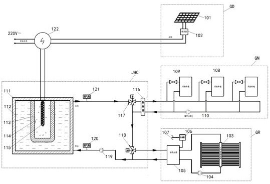
[0017] Embodiment 1, this embodiment is a solar indoor heating system with dual temperature heat storage, as shown in the appendix. figure 1 shown.

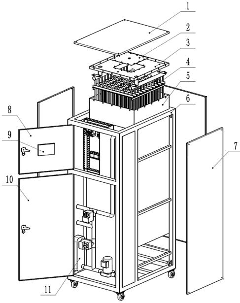
[0018] In the heating system, all the functions of the heat collection and heat exchange heat storage unit JHC are realized by the solar thermal cabinet of the present invention. The solar heat cabinet is composed of a heat collection and heat exchange heat storage device, a heat dissipation circulation device and a temperature control device. image 3 and attached Figure 4 shown. In this embodiment, the heat collection and heat exchange heat storage device is composed of an outer casing, a coil heat exchanger, a medium and low temperature phase change heat storage material, an inner casing, a high temperature heat medium, and an electric heater. inner shell ( image 3 not shown in the middle) is located in the center of the outer casing 5, and the medium and low temperature phase change heat storage material ( image 3 (no...

Embodiment 2

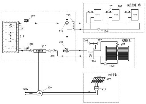
[0023] Embodiment 2, this embodiment is a solar indoor heating system with single-temperature heat storage and auxiliary electric heating, as shown in the appendix. figure 2 shown.

[0024]In this embodiment, the photoelectric collection unit, the photothermal collection unit, and the home heating unit are the same as those in the first embodiment.

[0025] The difference between the second embodiment and the first embodiment is that in the heat collection and heat exchange heat storage unit, only the medium and low temperature phase change heat storage material 212 is used to store heat, and the water flowing through the heat dissipation circulation pipeline is convected by the pipeline electric heater 217 medium for heating, see appendix Figure 5 . It is the photoelectric collection unit that provides power to the pipeline electric heater 217. When necessary, the grid-connected controller 220 can also automatically switch to 220V mains to supply power to the pipeline ele...


PUM

PropertyMeasurementUnit
Phase transition temperatureaaaaaaaaaa

Abstract

The invention relates to a solar heat cabinet which is characterized in that an inner shell of a heat collection, heat exchange and heat storage device of the heat cabinet is located in the center of an outer shell, a medium-low temperature phase change heat storage material is filled between the outer shell and the inner shell, a coil heat exchanger is arranged in the medium-low temperature phase change heat storage material, and a high-temperature heat medium is filled in the inner shell. And the electric heater is arranged in the high-temperature heat medium. A pipeline of the coil heat exchanger is communicated with a pipeline of the heat dissipation circulating device, and the pipeline of the heat dissipation circulating device and a pipeline of the heating device achieve heat exchange in the plate heat exchanger. And the electric heater is electrically connected with the inverter at the electric energy output end of the photovoltaic module through the grid-connected controller, and is also electrically connected with a mains supply power grid. Electric energy of the photovoltaic module and heat energy of the solar heat collector are efficiently collected and stored together, the structure is compact, and the size is small. The double-temperature heat storage scheme gives full play to the advantage of large heat capacity of the high-temperature heat medium, and effectively solves the problem that the output heat energy of the solar heat collector is low in winter, night and cloudy days.

Description

technical field [0001] The invention relates to a heating device that effectively utilizes solar energy, in particular to a solar thermal cabinet that can collect, store and utilize the electrical energy of photovoltaic modules and the thermal energy of solar collectors together. Background technique [0002] Making full use of solar energy to solve winter heating and long-term hot water supply in northern my country is a topic that has been continuously explored for a long time. [0003] Photovoltaic modules can convert solar energy into electrical energy, but the electrical energy generated by photovoltaic modules alone is not enough to ensure indoor heating in low temperature seasons, and the temperature of hot water generated by solar collectors absorbing sunlight energy will fluctuate with sunshine conditions, and it cannot be used. Guaranteed indoor heating demand in low temperature seasons. If the photovoltaic module electrical energy and the solar collector thermal ...

Claims


Application Information

Patent Timeline
IPC IPC(8): F24D15/00F24D18/00F24D19/00F24S10/30F24S60/10F24S20/40H02S40/44F24D101/40
CPCF24D15/00F24D19/00F24S10/30F24S60/10F24S20/40H02S40/44F24D2200/14F24D2200/08Y02E10/44Y02E10/50Y02E10/60
Inventor 胡国祥吕峰
Owner NANJING YUNENG NEW ENERGY TECH
Why Eureka
Try Eureka