Non-contact underground pipeline two-dimensional millimeter-level settlement real-time monitoring method

An underground pipeline, real-time monitoring technology, applied in the direction of climate sustainability, instruments, height/level measurement, etc., can solve the problems of monitoring data distortion, inability to real-time monitoring, low measurement accuracy, etc., to achieve low cost and high stability. , The effect of high monitoring accuracy

Pending Publication Date: 2022-06-07
河南省科学院同位素研究所有限责任公司 +2
0 Cites 0 Cited by

AI-Extracted Technical Summary

Problems solved by technology

However, the direct method usually needs to excavate the ground, find out the buried pipeline, fix the observation mark on the pipeline, and then monitor, which usually has the disadvantages of large amount of work and high c...

Method used

Acceleration sensor 6: base and connecting rod pass surface vibration to deep probe, probe vibrates up and down, directly affects monitoring result, obtains vibration displacement in real time by means of acceleration sensor, carries out data correction in real time, and then eliminates vibration to monitoring result influences.
[0083] T is the ultrasonic round-trip time for each high-precision ultrasonic ranging sensor 71 ranging. With the help of this device, th...

Abstract

The invention discloses a real-time monitoring method for two-dimensional millimeter-level settlement of a non-contact underground pipeline. The method comprises the following steps: step (1), acquiring the distance between a probe and the underground pipeline in the vertical direction in real time by a first ultrasonic distance measuring sensor; (2) calculating a settlement value of the underground pipeline in the vertical direction, and inverting a horizontal displacement value of the underground pipeline; (3) correcting the monitoring data in real time by a ground surface vibration correction module, and eliminating the influence of vibration on a monitoring result; step (4), a tilt correction module performs data correction on the monitoring result by using the tilt value of the horizontal plane of the probe; the system has a function of monitoring settlement of the underground pipeline in real time, and has the advantages of non-contact monitoring, high monitoring precision, simultaneous monitoring of displacement changes in vertical and horizontal directions, simple system device and installation process, high stability, good environmental adaptability, low later maintenance requirement, small hole, low cost, easy popularization and the like.

Application Domain

Using subsonic/sonic/ultrasonic vibration meansHeight/levelling measurement +1

Technology Topic

Underground pipelineMonitoring data +8

Image

  • Non-contact underground pipeline two-dimensional millimeter-level settlement real-time monitoring method
  • Non-contact underground pipeline two-dimensional millimeter-level settlement real-time monitoring method
  • Non-contact underground pipeline two-dimensional millimeter-level settlement real-time monitoring method

Examples

  • Experimental program(5)

Example Embodiment

[0058] Example 1
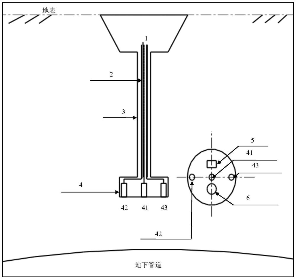
[0059] refer to figure 1 , The non-contact underground pipeline two-dimensional millimeter-level settlement real-time monitoring system includes sensor array probes, connecting rods 3, underground sound velocity vertical distribution real-time monitoring devices, base 1, wireless transmission and monitoring terminals. The sensor array probe is used as the main detection unit, including three ultrasonic ranging sensors (41, 42, 43), one acceleration sensor 6 and one inclination sensor 5. The sensing surfaces of the three ultrasonic ranging sensors face downward. The first ultrasonic ranging sensor 41 obtains the distance between the probe and the underground pipeline in the vertical direction in real time, and ΔD1i is the settlement value of the underground pipeline in the vertical direction; the monitoring terminal includes a foreign object extrusion and intrusion identification module, surface vibration correction module and tilt correction module.
[0060] The second ultrasonic ranging sensor 42 and the third ultrasonic ranging sensor 43 are respectively used to obtain the distance between the two sensors and the underground pipeline in the vertical direction, and then calculate the settlement value of the underground pipeline in the vertical direction, and invert The horizontal displacement value of the underground pipeline, and the acquired data is sent to the foreign object extrusion and intrusion identification module. After processing, the foreign object extrusion and intrusion identification module identifies whether there is foreign object extrusion and intrusion between the probe and the underground pipeline. The base 1 and the connecting rod 3 transmit the surface vibration to the acceleration sensor 6 buried deep in the ground. The sensing surface of the acceleration sensor 6 faces upwards. The vibration displacement is obtained in real time with the help of the acceleration sensor 6 and sent to the surface vibration correction module. The correction module performs real-time correction on the monitoring data to eliminate the influence of vibration on the monitoring results; the sensing surface of the tilt sensor 5 is facing upward, and the tilt value of the horizontal plane of the sensor array probe is monitored in real time and sent to the tilt correction module. The tilt correction module uses the tilt of the horizontal plane of the probe. The data is corrected for the monitoring results. The data collected by the sensors in the sensor array probe is wirelessly transmitted to the monitoring terminal through the GPRS/4G module in the base; the monitoring terminal also has the function of map access to monitor the settlement information of all pipelines in multiple places in real time. When the information is greater than the set threshold, the monitoring terminal will automatically alarm, automatically send a short message to the receiving terminal of the designated person, and the receiving person can deploy personnel for manual review according to the location information.
[0061] It can be seen from the ultrasonic ranging formula L=0.5×V×T that the velocity V is one of the most important factors affecting the accuracy of the ultrasonic ranging test, and uncertain factors such as temperature, humidity, and soil density will affect the value of V. Unlike air and water media, which are relatively uniform, soil temperature, humidity, density, etc. will change continuously with depth. Therefore, the velocity V is closely related to the depth, and establishing the corresponding relationship between them is the premise to achieve high-precision monitoring.
[0062] The real-time monitoring device for the vertical distribution of underground sound speed is used to obtain the speed of sound propagation at different depths in the monitoring area in real time, and establish a correlation function, which is then used to monitor the settlement of each monitoring channel. Uncertainties such as soil density, climate and season have the least influence on the settlement value. It can avoid many uncertainties caused by the existing calibration methods, and minimize the influence of temperature, water content, density, and seasonal changes on the sound transmission rate, which is an important guarantee for the realization of high-precision settlement monitoring of underground pipelines.
[0063] The first ultrasonic ranging sensor 41: the initial distance between the probe and the underground pipeline is D 1o , the distance between the probe and the underground pipeline obtained by real-time monitoring in the vertical direction is D 1i , its relative initial distance D 1o The change value of ΔD 1i , the change value is ΔD 1i is the settlement value of the underground pipeline along the vertical direction.
[0064] The difference between the vertical displacement of the second ultrasonic ranging sensor 42 and the third ultrasonic ranging sensor 43 relative to the vertical displacement of the first ultrasonic ranging sensor 41 is ΔD, respectively. 12i and ΔD 13i , the real-time acquisition of these two values ​​has the following important functions: (1) During debugging and installation, the sensor array probe can be precisely controlled to be directly above the top of the underground pipeline, and the monitoring error in this area is the smallest; (2) During debugging and installation, it can be precisely controlled The three ultrasonic sensors in the probe are distributed along the direction perpendicular to the axis of the underground pipeline, at this time △D 12i and ΔD 13i It has the maximum value; (3) Obtain the horizontal displacement and direction of the pipeline during the subsidence process of the underground pipeline, and the true value of the vertical underground pipeline settlement; (4) Identify whether there is an underground foreign object squeezed and intruded between the probe and the underground pipeline .
[0065] Acceleration sensor 6: The base and connecting rod transmit the surface vibration to the deep probe, and the probe vibrates up and down, which directly affects the monitoring results. The vibration displacement is obtained in real time with the help of the acceleration sensor, and the data is corrected in real time, thereby eliminating the impact of vibration on the monitoring results.
[0066] The inclination sensor 5 monitors the inclination value of the horizontal plane of the probe in real time, and performs data correction when the inclination angle affects the monitoring result.
[0067] The connecting rod is rigid and hollow, and the sensor wire passes through the center of the connecting rod and is connected with the base.
[0068] The method of using the real-time monitoring system for two-dimensional millimeter-level settlement of non-contact underground pipelines of the present invention:
[0069] Use professional instruments to find out the location of the underground pipeline to be monitored, and excavate a 10-15cm hole;
[0070] Clean up the soil on the upper part of the tunnel, and stop digging when the distance from the underground pipeline is ~10cm (not strictly required);
[0071] Use the ultrasonic ranging sensor to check whether there are any foreign objects such as bricks in the remaining soil. If there is no foreign object, the remaining soil in the tunnel does not need to be taken out; compaction.
[0072] Place the lower surface of the sensor array probe 4 on the top of the remaining soil in the tunnel. According to the ultrasonic sensor △D 12i and ΔD 13i The size of the value adjusts the direction and position of the probe to ensure that the ultrasonic sensor is distributed along the direction perpendicular to the axis of the underground pipeline, and the probe is as close to the top of the underground pipeline as possible.
[0073] Adjust the level of the lower surface of the probe. Debug, connect. Soil, compact. The base is fixed, and the anti-vibration and anti-tilt treatment is carried out. data transmission. Real-time monitoring through computer and mobile phone.

Example Embodiment

[0074] Example 2
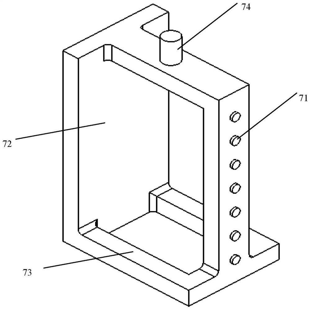
[0075] refer to figure 2 , the underground sound velocity vertical distribution real-time monitoring device, divided into left and right parts, the right side is installed a series of high-precision ultrasonic ranging sensors 71 at different heights from top to bottom to form an array sensor, the left is an ultrasonic reflection plate 72, ultrasonic reflection plate The distance L between 72 and the array sensor is a fixed value.
[0076] Dig a vertical hole in the roadside, flower bed and other places where holes are easy to be opened, put the device into the soil, adjust the ultrasonic reflector 72 and the array sensor to the vertical direction, fill the soil, and compact.
[0077] V=2L/T, T is the ultrasonic round-trip time, which is measured by each ultrasonic sensor, and then the real-time propagation rate of ultrasonic waves at different depths can be calculated.
[0078] The real-time corresponding function of velocity V and depth is obtained: y=V(x).
[0079] The real-time corresponding function of velocity V and time is obtained: y=V(t).
[0080] In this way, the influence of various uncertain factors on V is minimized, thereby improving the monitoring accuracy of pipeline settlement.
[0081] Affected by temperature, humidity, soil density, etc., the speed of sound propagation in soil at different depths is likely to have a gradient distribution (y=V(x)). The change in time is inversely proportional to the change in the speed of sound. Therefore, there is also a corresponding functional relationship between the sound propagation velocity and time at different depths (y=V(t)). First, the function y=V(t) is obtained by using the real-time monitoring device for the vertical distribution of the underground sound speed, and then the formula for the settlement distance of each monitoring point that is not affected by external factors is obtained by using this function:
[0082]
[0083] T is the ultrasonic round-trip time when each high-precision ultrasonic ranging sensor 71 measures the distance. With the help of this device, the real propagation rate of different depths under the surface can be monitored in real time, and there is no need to consider the influence of uncertain factors such as temperature, humidity, soil density, etc., and the influence of sound speed changes on the ranging accuracy is minimized. An important guarantee for accurate underground ranging. Using this integral formula for distance measurement, even if there is water in the deep part of summer and dry soil in the shallow part, high-precision and high-accuracy real-time data can be obtained

Example Embodiment

[0084] Embodiment 3 Simultaneous monitoring method for horizontal displacement and vertical displacement of pipeline
[0085] 3.1 Displacement algorithm when only vertical settlement
[0086] Horizontal displacement: △x=0;
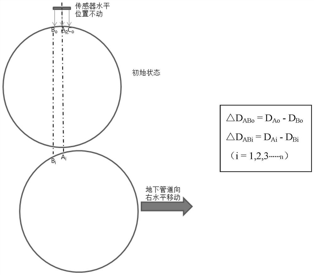
[0087] Vertical displacement: △D i =D Ai -D Ao =D Bi -D Bo =D Ci -D Co.
[0088] A, B and C are the positions where the ultrasonic waves emitted by the three sensors (the first, second and third ultrasonic ranging sensors 41, 42 and 43) hit the underground pipeline respectively, D Ao , D Bo , D Co They are the vertical distances between the three sensors and A, B, and C after the equipment has just been debugged, D Ai , D Bi , D Ci are the vertical distances between the three sensors and A, B, and C, which are monitored in real time during the monitoring process.
[0089] 3.2 The necessity of horizontal displacement monitoring
[0090] Necessity of monitoring: (1) During the settlement process of the pipeline, a small amount of horizontal displacement is likely to occur; (2) Because the surface of the pipeline is a curved surface, the horizontal movement will cause more or less displacement in the vertical direction ( image 3); (3) Although a small amount of horizontal displacement will not have a great impact on the measurement results in the vertical direction, for high-precision settlement monitoring (≤1mm), the displacement change in the horizontal direction is an important factor that must be considered. factor.
[0091] like image 3 As shown in the figure, the underground pipeline has no up and down settlement, only horizontal movement to the right occurs, in which the sensor probe is fixed, and there is no horizontal displacement change. image 3 The position A where the ultrasonic wave from the middle sensor hits the pipe i , as the pipe moves horizontally to the right, A i relative to the initial position A o will become more and more to the left, and the difference between the two displacements in the vertical direction △D Ai (△D Ai =∣D Ai -D Ao ∣) will become larger and larger, which explains two problems: (1)△D Ai becomes larger as the horizontal displacement becomes larger, and there is a one-to-one correspondence ( Figure 4 ); (2)△D Ai It is the contribution value of the horizontal movement of the underground pipeline to the settlement in the vertical direction. If this value is not deducted, the monitoring value of the settlement of the underground pipeline will be over-counted or under-counted.
[0092] 3.3 Calculation of horizontal displacement using vertical settlement
[0093] From the above, it can be seen that ΔD Ai becomes larger as the horizontal displacement becomes larger, and there is a one-to-one correspondence ( Figure 4 ). Therefore, the monitoring point (A i ) real-time abscissa, see the calculation principle Figure 5 , the corresponding formula is:
[0094] X 2 +Y 2 =R 2 (1)
[0095] R is the radius of the monitored underground pipeline, the unit is mm, which can be obtained from formula (1):
[0096]
[0097] From formula (2), we can get:
[0098]
[0099]
[0100] From formula (3) and formula (4), we can get:
[0101]
[0102] Assuming that the fixed horizontal displacement value between the first ultrasonic ranging sensor 41 and the third ultrasonic ranging sensor 43 in the sensor array is d, then:
[0103] X Ai +d=X Ci (6)
[0104] △D i The difference value of the distance in the vertical direction obtained by real-time monitoring of the first ultrasonic ranging sensor 41 and the third ultrasonic ranging sensor 43, namely:
[0105] △D i =Y Ai -Y Ci (7)
[0106] From formulas (5), (6) and (7), the vertical displacement and X can be obtained Ai :
[0107]
[0108] It can be known from formula (8): (1) Real-time monitoring of the difference ΔD of the vertical displacement of the underground pipeline with the help of three ultrasonic sensors i The real-time abscissa value X can be calculated Ai (2) When the system has just been debugged, the first ultrasonic sensor 41 may not be installed on the upper end of the top of the underground pipeline, and its initial abscissa can also be calculated by formula (8) X Ao; (3) Compare X Ai and X Ao The direction and absolute displacement value of the horizontal movement of the underground pipeline can be obtained, namely:
[0109] Pipeline right motion discrimination method: X AiX Ao
[0110] Discrimination method of pipe movement to the left: X Ai Ao
[0111] Horizontal displacement value: △X 水平 =∣X Ai -X Ao ∣
[0112] Contribution of horizontal displacement to vertical settlement of pipeline:
[0113]
[0114] The true value of vertical underground pipeline settlement △D 真值 :
[0115] Y Ai Ao , when, △D 真值 =△D Ai -∣Y Ai -Y Ao ∣
[0116] Y AiY Ao , when, △D 真值 =△D Ai +∣Y Ai -Y Ao ∣
[0117] △D Ai It is the displacement change value in the vertical direction read in real time by the ultrasonic sensor.
[0118] Image 6 , Figure 7 and Figure 8 is the ΔD obtained by real-time monitoring of underground pipelines with diameters of 0.5m, 1m and 2m obtained according to formula (8). i with X Ai Value function relationship diagram, it can be found from the figure: (1) △D i with X Ai There is a one-to-one correspondence; (2) 0.5m, 1m and 2m underground pipelines, when the X Ai △D when the value is in the interval of ±70mm, ±200mm and ±400mm respectively i with X Ai has a good correlation, and X Ai The smaller the value, the △D i with X Ai The better the linear correlation, the smaller the error of correcting the vertical displacement value with the horizontal displacement change value; (3) the larger the diameter of the underground pipeline, the larger the applicable range of measurement; (4) the △D obtained by the vertical direction monitoring i value, use Image 6 , Figure 7 and Figure 8 The function in can be directly calculated to obtain X Ai value. (5) The larger the diameter of the pipeline, the closer the ultrasonic sensor for monitoring is to the top of the pipeline, and the smaller the influence of the horizontal movement of the pipeline on the vertical displacement measurement will be.

PUM

no PUM

Description & Claims & Application Information

We can also present the details of the Description, Claims and Application information to help users get a comprehensive understanding of the technical details of the patent, such as background art, summary of invention, brief description of drawings, description of embodiments, and other original content. On the other hand, users can also determine the specific scope of protection of the technology through the list of claims; as well as understand the changes in the life cycle of the technology with the presentation of the patent timeline. Login to view more.

Similar technology patents

Water conservancy and hydropower project dam stability monitoring equipment based on cloud computing

PendingCN113503910ARealize dynamic monitoringImprove monitoring accuracy
Owner:福建润闽工程顾问有限公司

High-sanitary-standard medicinal container inspection device

InactiveCN107328732AImprove monitoring accuracy
Owner:广州燃烧医疗技术开发有限公司

Classification and recommendation of technical efficacy words

  • Improve monitoring accuracy
  • Simplify the installation process

Self-cleaning sowing device and real-time monitoring method thereof

InactiveCN101361423AImprove monitoring accuracyKeep monitoring performance
Owner:CHINA AGRI UNIV

Lithium battery energy storage container with fire isolation function and fire isolation method thereof

PendingCN110165110AImprove monitoring accuracyavoid excessive measures
Owner:WUHAN NARI LIABILITY OF STATE GRID ELECTRIC POWER RES INST +2

Infusion control system and method based on physiological information feedback

ActiveCN104147661AImproving the workload of medical care is hugeImprove monitoring accuracy
Owner:FOURTH MILITARY MEDICAL UNIVERSITY

Multifunctional integrated power supply device

InactiveCN102522797ASimplify the installation processImprove scalable performance
Owner:义乌市八方电力设备制造有限公司

Fixed anti-skid locking device and multifunctional rod comprising same

ActiveCN112212296ASimplify the installation processEasy to adjust the position
Owner:ZHEJIANG JINGRI LIGHTING TECH

Air deflector driving mechanism and electrical product using same

InactiveCN106016658ASimplify the installation processReduce the use of parts
Owner:GREE ELECTRIC APPLIANCES INC OF ZHUHAI
Why Eureka
Try Eureka