Check patentability & draft patents in minutes with Patsnap Eureka AI!

Circuit breaker overload protection structure

An overload protection and circuit breaker technology, which is applied in the direction of protection switches, protection switch operation/release mechanisms, emergency protection devices, etc., can solve problems such as long reset time, high cost, failure of product overload protection characteristics, etc., and achieve high reliability. Effect

Pending Publication Date: 2022-06-07
ZHEJIANG CHINT ELECTRIC CO LTD
View PDF0 Cites 0 Cited by
  • Summary
  • Abstract
  • Description
  • Claims
  • Application Information

AI Technical Summary

Problems solved by technology

The advantages of using thermal bimetal are simple structure, low cost, and the action characteristics of bimetal have nothing to do with the power supply voltage; the disadvantage is that the overload action characteristics are greatly affected by the ambient temperature and altitude, poor thermal stability, and long reset time after action.
[0003] The overload characteristics of intelligent circuit breakers on the existing market basically use current transformers or manganese-copper alloy sheets to sample the loop current. The advantage is that the sampling accuracy is high, the data can be uploaded and recorded, and the action time can be set, which is affected by the ambient temperature. Small, intelligent and modular control can be realized; the disadvantage is that the accuracy of sampling current transformer is high, the cost is high, and the structure is relatively complicated. When the power supply voltage fails or the electronic components on the circuit board fail, the overload protection feature of the product will fail

Method used


Image

  • Circuit breaker overload protection structure
  • Circuit breaker overload protection structure
  • Circuit breaker overload protection structure

Examples


Embodiment Construction

[0021] Attached to the following Figures 1 to 4 The given examples further illustrate the specific implementation of the circuit breaker overload protection structure of the present invention. The overload protection structure of the circuit breaker of the present invention is not limited to the description of the following embodiments.

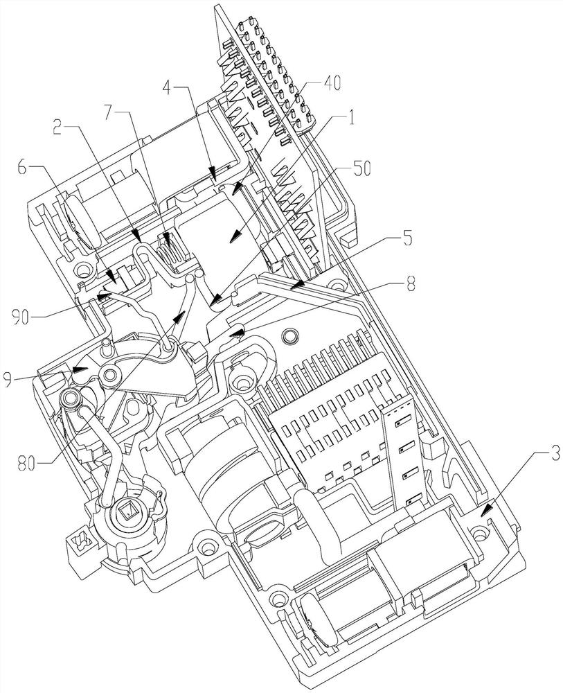
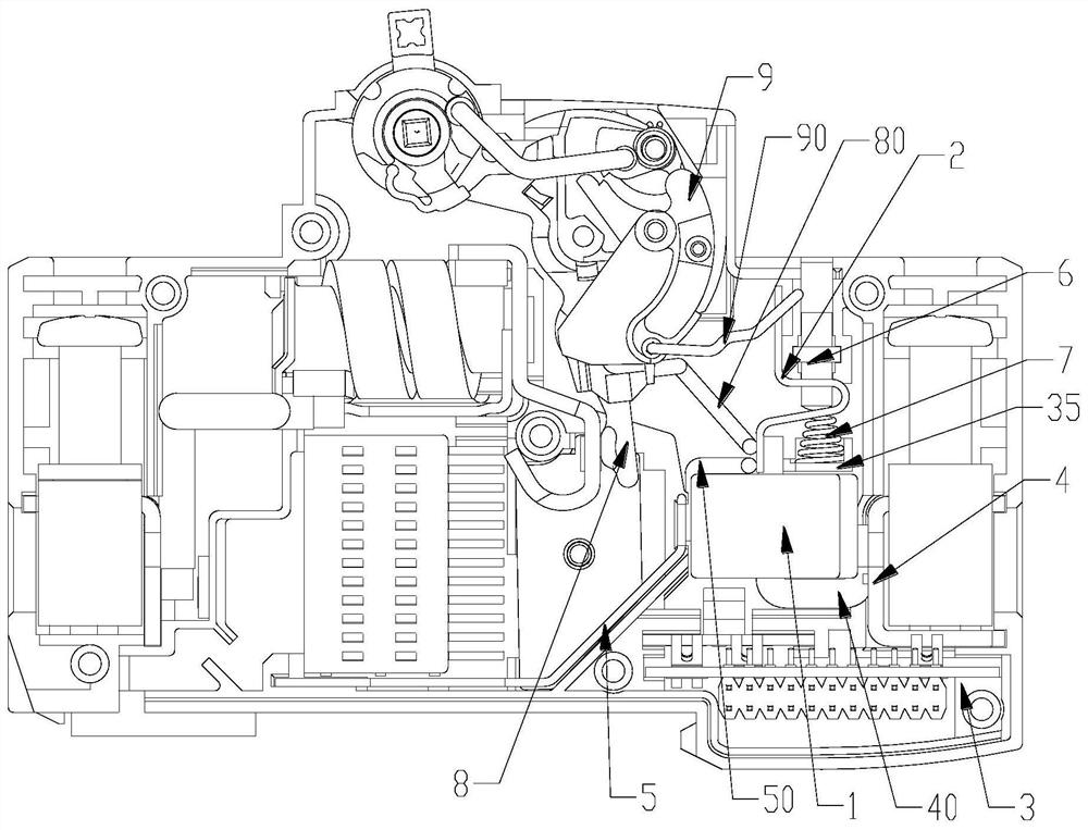
[0022] like Figure 1-4 As shown, the circuit breaker overload protection structure of the present invention includes a current transformer 1 installed in the base 3, a bimetallic sheet 2, a hard wire 40, a wiring board 4, an arc striking board 5, an adjusting screw 6, a return spring 7 and The movable contact 8 and the lock 9 of the operating mechanism, one end of the bimetal 2 is the bendable portion 21 that is drivingly connected with the lock 9 of the operating mechanism, the other end of the bimetal 2 is the connecting portion 25, the hard wire 40 One end is connected to the wiring board 4, the other end of the hard wire 40 is connect...


PUM


Abstract

The circuit breaker overload protection structure comprises a current transformer, a bimetallic strip and a hard wire which are installed in a base, one end of the bimetallic strip is a bendable part in driving connection with a lock catch of a circuit breaker operating mechanism, the other end of the bimetallic strip is a connecting part, one end of the hard wire is connected with a wiring board, and the other end of the hard wire is connected with a power supply. The other end passes through the current transformer and then is connected with the connecting part of the bimetallic strip, and the connecting part of the bimetallic strip is connected with the moving contact. The circuit breaker overload protection structure is arranged between the moving contact and the wiring board, the bimetallic strip and the current transformer are arranged at the same time, and overload protection is achieved through the bimetallic strip under the condition that a control circuit board has no power supply voltage or the power supply voltage fails or components of the circuit board fail. And under the condition that the control circuit board has power supply voltage, overload protection is mainly realized by the current transformer, the product overload characteristic has dual protection, and the overload protection characteristic is higher in reliability.

Description

technical field [0001] The invention relates to the technical field of low-voltage electrical appliances, in particular to an overload protection structure of a circuit breaker. Background technique [0002] A circuit breaker is generally composed of a contact system, an arc extinguishing system, an operating mechanism, a thermal tripping system and an electromagnetic system. The electromagnetic system has the function of short-circuit protection. When a short circuit occurs in the electric circuit where the small circuit breaker is located, the current becomes larger, and the magnetic force generated by the large current overcomes the reaction spring, so that the coil ejector pushes the operating mechanism to act, and the circuit breaker trips instantaneously. The thermal tripping system has the function of overcurrent protection. Generally, thermal bimetals are used. Using the long delay and inverse time characteristics of the bimetals, when the overload current passes thr...

Claims


Application Information

Patent Timeline
IPC IPC(8): H01H71/12H01H71/16
CPCH01H71/125H01H71/16
Inventor 夏晓敏邵江华涂兵邓彦军张建伟李达
Owner ZHEJIANG CHINT ELECTRIC CO LTD
Features
  • R&D
  • Intellectual Property
  • Life Sciences
  • Materials
  • Tech Scout
  • Unparalleled Data Quality
  • Higher Quality Content
  • 60% Fewer Hallucinations
Learn More