
Elastic micro-beam resonator with maximum thermoelastic damping

A thermoelastic damping and resonator technology, applied in the direction of impedance network, electrical components, etc., can solve the problems of large size, large vibration displacement overshoot, large amplitude, etc., and achieve the effect of maximizing thermoelastic damping

Pending Publication Date: 2022-06-07
SOUTHEAST UNIV
View PDF0 Cites 0 Cited by
  • Summary
  • Abstract
  • Description
  • Claims
  • Application Information

AI Technical Summary

Problems solved by technology

[0004] In the prior art, the selection of length and thickness (or radius) in the microbeam design process is based on experience, which leads to uncontrollable thermoelastic damping of the device. If the thermoelastic damping of the designed resonator is small, the amplitude Larger and larger in size, resulting in a large overshoot of vibration displacement, which cannot meet the needs of use

Method used


Image

  • Elastic micro-beam resonator with maximum thermoelastic damping
  • Elastic micro-beam resonator with maximum thermoelastic damping
  • Elastic micro-beam resonator with maximum thermoelastic damping

Examples


Embodiment 1

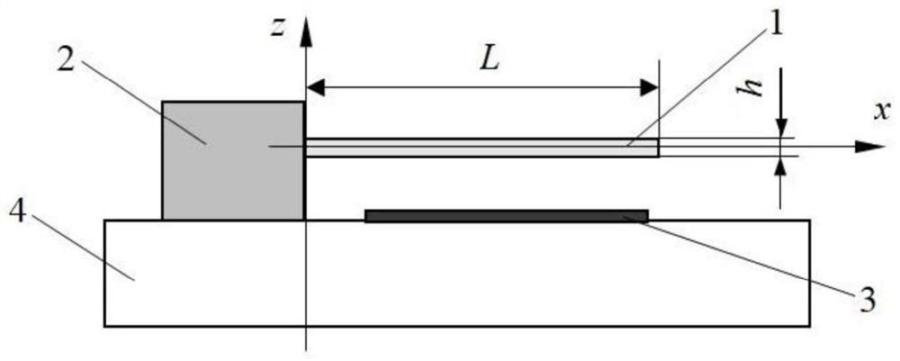
[0031] like figure 2 As shown, the structure of the elastic micro-beam resonator is as follows: it includes an elastic cantilever micro-beam 1 (vibrator) with a specific length and a specific thickness, a fixed support 2 , a driving electrode 3 and a substrate 4 . One end of the elastic cantilever microbeam 1 is connected to the substrate 4 through the fixed support 2 . figure 2 The symbols L and h in the middle represent the length and thickness of the elastic cantilever microbeam 1 respectively. The elastic cantilever microbeam 1 deforms and vibrates along the thickness h direction under the action of electrostatic force. The fixed support 2 is relatively rigid and keeps the elastic cantilevered microbeam 1 above the drive electrode 3 .

[0032] The cross-section of the elastic cantilever micro-beam 1 is rectangular, and the thickness of the rectangle satisfies the formula (1). and dissipated, that is, the vibration mechanical energy of the micro-beam is transformed int...

Embodiment 2

[0065] still see figure 2 , same as Example 1, the difference is that the cross-section of the elastic cantilever micro-beam 1 is circular, and the cross-sectional radius satisfies the above formula (2), the elastic cantilever micro-beam 1 produces thermoelastic damping when it bends and vibrates, and the heat dissipation in the process of heat dissipation The thermal relaxation time is Substituting equation (2) into equation (5), we get That is to say, the structure of the beam satisfies ωτ≈1 at this time, so it has the maximum thermoelastic damping.

[0066] The length of the elastic cantilever microbeam 1 with maximum thermoelastic damping is determined as follows:

[0067] The Nth order natural frequency of the elastic cantilever microbeam 1 can also be expressed as:

[0068]


PUM


Abstract

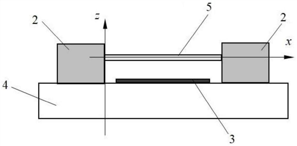
The invention relates to an elastic micro-beam resonator with maximum thermoelastic damping, which comprises an oscillator, a driving electrode and a substrate, the oscillator is an elastic cantilever micro-beam or a micro-beam clamped at two ends, and the elastic micro-beam resonator is characterized in that the cross section of the oscillator is rectangular or circular; when the cross section of the vibrator is rectangular, the thickness of the cross section of the vibrator is round, k and Cv of the radius of the cross section are the heat conductivity coefficient and the heat capacity per unit volume respectively, and omega is the working frequency. According to the invention, the relationship among the working frequency, the oscillator length, the thickness (or the radius of the cross section) and the thermoelastic damping is constructed, and the thermoelastic damping of the elastic micro-beam resonator is maximized through the quantitative design of the size and the length of the cross section of the oscillator.

Description

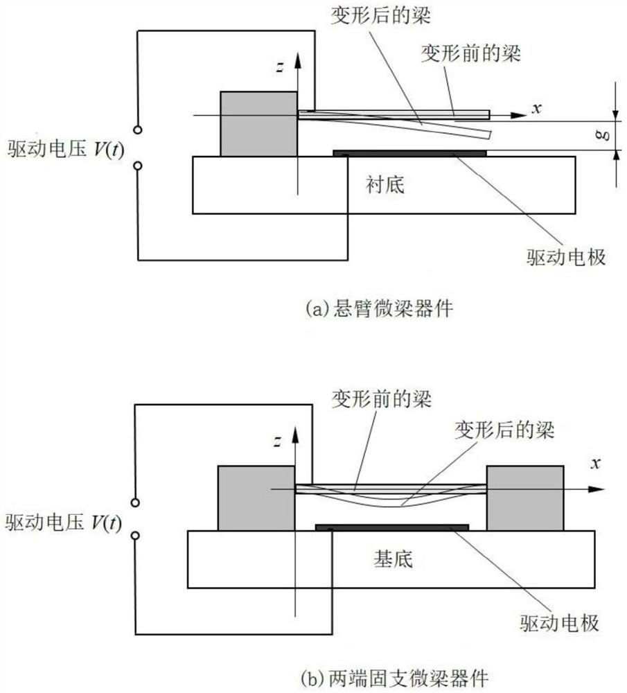
technical field [0001] The invention relates to the field of micro-mechanical electronic systems (MEMS), in particular to an elastic micro-beam resonator with the largest thermoelastic damping. Background technique [0002] Bending vibration cantilever microbeams and end-clamped microbeams are the core parts of many micromechanical resonant devices. like figure 1 (a) and (b) are schematic diagrams of the structure of the cantilever microbeam resonator and the microbeam resonator supported at both ends, respectively. The microbeam in the resonator vibrates at its natural frequency, and the amount of damping directly affects the resonance peak. The amount of damping can also be measured by the quality factor Q. [0003] In general, the quality factor ξ is the damping ratio. The higher the quality factor, the less damped the device will be. For resonators, the damping is large and small, each with its own advantages and disadvantages. The advantages of the device with s...

Claims


Application Information

Patent Timeline
Patent Type & Authority Applications(China)
IPC IPC(8): H03H9/02H03H9/09
CPCH03H9/02244H03H9/02433H03H9/09H03H2009/02251
Inventor 李普张宁卢熹孙蓓蓓张建润
Owner SOUTHEAST UNIV
Learn More