Office building corridor security camera

A technology for cameras and office buildings, used in image communication, cleaning methods using liquids, televisions, etc., can solve problems such as manual cleaning, security cameras cannot be cleaned, and no protective components, etc., to achieve the effect of strengthening the cleaning effect.

Pending Publication Date: 2022-06-07
陈烋烈
0 Cites 0 Cited by

AI-Extracted Technical Summary

Problems solved by technology

[0004] 1. The existing security camera does not have suitable protective components during use, which makes it vulnerable to external shocks and damage ...

Method used

...

Abstract

The invention discloses an office building corridor security and protection camera, and relates to the technical field of security and protection equipment, the office building corridor security and protection camera comprises a main body device, the main body device is internally provided with a camera, the upper surface of the camera is provided with an external protection shell, and the front surface of the camera is provided with a front protection net; and one side of the front protection net is fixedly connected with a side protection net. According to the invention, the first buffer spring, the first buffer composite elastic sheet, the second buffer composite elastic sheet and the auxiliary spring rod are used for buffer protection, and then the front protective net is used for protecting the lens, so that the problem that the lens or internal elements are damaged due to the fact that the existing security camera is easily subjected to external impact in the use process is solved, and the service life of the security camera is prolonged. And a first micro cleaning motor and a second micro cleaning motor are started to respectively drive a first cleaning brush plate and a second cleaning brush plate to alternately rotate for cleaning, and an electric control valve is started to spray cleaning water in a water inlet pipe onto the lens during cleaning, so that the cleaning effect is enhanced.

Application Domain

Television system detailsColor television details +3

Technology Topic

Electric machineryStructural engineering +2

Image

  • Office building corridor security camera
  • Office building corridor security camera
  • Office building corridor security camera

Examples

  • Experimental program(2)

Example Embodiment

[0038] Example 1
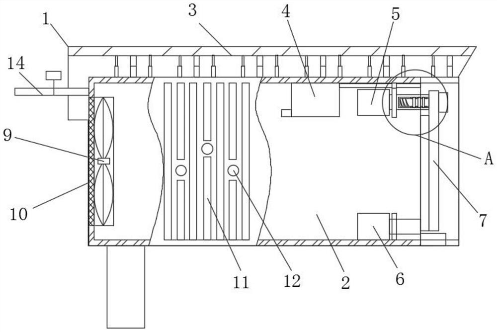
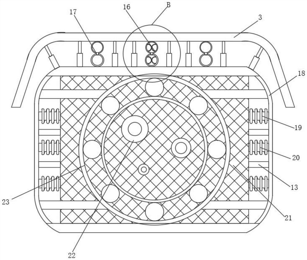
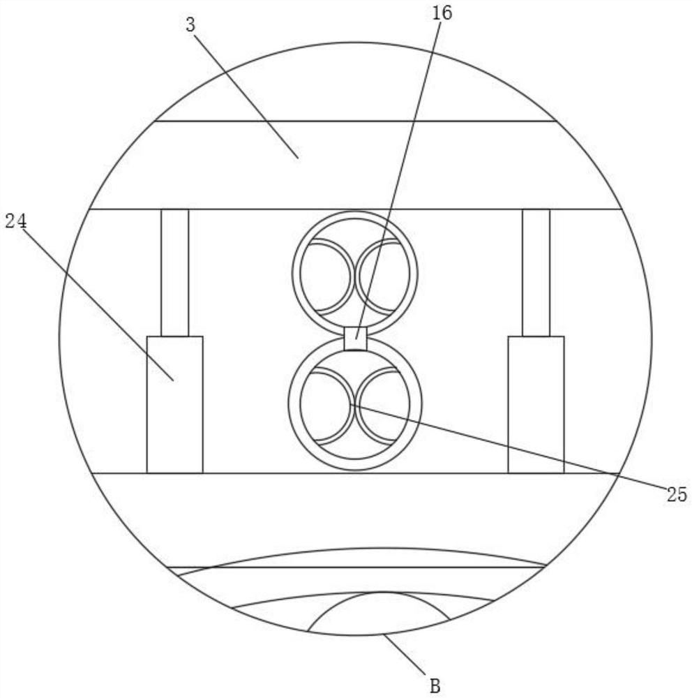
[0039] like Figure 1-8As shown, the present invention provides an office building corridor security camera, including a main device 1, a camera 2 is arranged inside the main device 1, an external protective shell 3 is arranged on the upper surface of the camera 2, and a front surface is arranged on the front of the camera 2. A protective net 21 is placed, one side of the front protective net 21 is fixedly connected with a lateral protective net 18, the inner wall of the lateral protective net 18 is fixedly connected with a first buffer spring 19, and a second buffer is arranged below the first buffer spring 19. For the spring 20 , the top of the inner wall of the outer protective shell 3 is fixedly connected with a first buffer composite elastic piece 16 , and the inner wall of the first buffer composite elastic piece 16 is fixedly connected with a supporting arc elastic piece 25 .
[0040] When the outer wall of the camera 2 is impacted, the side protection net 18 transmits the impact to the inside of the first buffer spring 19, so that it deforms to generate a reaction force to offset the impact, and protect the camera 2 from the side. , is protected by the external protective shell 3, and the first buffer composite shrapnel 16, the second buffer composite shrapnel 17 and the auxiliary spring rod 24 are used for buffer protection. When the front of the camera 2 is impacted, the front protective net 21 is used to protect the lens. 35 for protection, and at the same time, a reserved monitoring through hole 22 opened on the front protective net 21 avoids the influence on the probe in the camera 2 .
[0041] A lens 35 is fixedly connected to the right inner wall of the camera head 2, a first cleaning brush plate 7 is movably connected to the front of the lens 35, and a rotating installation block 30 is movably connected to the top inner wall of the first cleaning brush plate 7, and the left outer wall of the rotating installation block 30 is movably connected. A rotating installation cylinder 27 is threadedly connected, and a second cleaning brush 8 is provided on one side of the first cleaning brush plate 7. When the lens 35 needs to be cleaned, the first micro cleaning motor 5 and the second micro cleaning motor 6 are activated, respectively. The first cleaning brush plate 7 and the second cleaning brush plate 8 are driven to rotate alternately for cleaning. During cleaning, the electric control valve is opened to spray the cleaning water in the water inlet pipe 14 onto the lens 35 to enhance the cleaning effect.
[0042] The front side of the front protection net 21 is fixedly connected with a reinforcement ring frame 23 , the front side of the front protection screen 21 is provided with a reserved monitoring through hole 22 , and the left end of the first buffer spring 19 is fixedly connected with the outer wall of the camera 2 . The side is provided with a side mounting hole 12, the inner wall of the side mounting hole 12 is fixedly connected with a side mounting rod 13, one end of the side mounting rod 13 is fixedly connected with the inner wall of the side protection net 18, and the outer wall of the camera 2 is fixedly connected with a Lateral cooling fins 11 .
[0043] One side of the first buffering composite elastic sheet 16 is provided with an auxiliary spring rod 24, one side of the auxiliary spring rod 24 is provided with a second buffering composite elastic sheet 17, and the top of the auxiliary spring rod 24 is fixedly connected with the top of the inner wall of the external protective shell 3, A first micro cleaning motor 5 is fixedly connected to the left side of the rotating installation cylinder 27, a second micro cleaning motor 6 is arranged below the first micro cleaning motor 5, and a built-in cooling fan 9 is fixedly connected to the inner wall of the camera 2. The built-in cooling fan 9 The left side is fixedly connected with the dustproof net 10. After the cleaning is completed, the micro air pump 4 is started, and the hot air generated by the operation of the internal components of the camera 2 extracted by the micro air pump 4 is transported to the bristles of the bristle plate 31 through the drying double air pipe 33 to speed up the operation. Dry and easy to use next time, start the built-in cooling fan 9 to transport the heat generated inside the camera 2 to the outside, and use it with the lateral cooling fins 11 to speed up the heat dissipation efficiency and avoid the accumulation of internal heat, which will cause the internal components of the camera 2. damage.

Example Embodiment

[0044] Example 2
[0045] like Figure 1-8 As shown, on the basis of Embodiment 1, the present invention provides a technical solution: preferably, the inner wall of the rotating installation cylinder 27 is fixedly connected with the installation limit elastic piece 28, and the outer wall of the left end of the rotating installation block 30 is fixedly connected with a rubber resistance ring. 29. The outer wall of the rubber baffle ring 29 is movably connected to the outer wall of the installation limit elastic piece 28, the inner wall of the first cleaning brush plate 7 is movably connected with a bristle plate 31, and the left inner wall of the first cleaning brush plate 7 is fixedly connected with a fixed magnet block. 40. A moving magnet block 41 is movably connected to the right side of the fixed magnet block 40. The right side of the moving magnet block 41 is fixedly connected to the left end of the bristle plate 31, and the inner wall of the right end of the first cleaning brush plate 7 is fixedly connected to a limit block 43. The right end of the plate 31 is fixedly connected with an installation push-pull block 45, the upper surface of the installation push-pull block 45 is provided with a downward moving groove 46, the inner wall of the downward moving groove 46 is movably connected with a pressing block 47, and the bottom surface of the pressing block 47 is fixedly connected with a linkage rod 49. A bearing groove 50 is formed on the bottom surface of the inner wall of the downward moving groove 46 .
[0046] A pressing return spring 48 is movably connected to the outer wall of the interlocking rod 49 , the top of the pressing return spring 48 is fixedly connected with the bottom surface of the pressing block 47 , and the left end of the interlocking rod 49 is fixedly connected with a clamping block 44 .
[0047] When replacing the bristle plate 31 in the first cleaning brush plate 7 , it is only necessary to press the pressing blocks 47 on both sides. The pressing blocks 47 move down to compress and press the return spring 48 , and at the same time drive the linkage rod 49 to move down on the inner wall of the bearing groove 50 , the linkage rod 49 drives the snap block 44 to move down to release the restriction on the limit block 43, and then pulls and installs the push-pull block 45 to complete the disassembly of the bristle plate 31. The left end is docked with the installation port of the first cleaning brush plate 7 and then pressed to complete the installation.
[0048] The top of the lens 35 is provided with a water inlet pipe 14, the outer wall of the water inlet pipe 14 is fixedly connected with an electric control valve, the left side of the first cleaning brush plate 7 is provided with a drying dual air distribution pipe 33, and the end of the drying dual air distribution pipe 33 is fixedly connected with a The micro air pump 4, the bottom surface of the inner wall of the camera 2 is provided with a water collection tank 36, the inner wall of the water collection tank 36 is fixedly connected with a built-in filter screen 38, the inner wall bottom surface of the water collection tank 36 is fixedly connected with a guide block 39, and the inner wall of the water collection tank 36 is provided with drainage holes 37. The sewage generated by cleaning is collected into the water collecting tank 36 after being filtered by the built-in filter screen 38, and is discharged through the drainage hole 37.
[0049] Let's talk about the working principle of the corridor security camera in the office building in detail.
[0050] like Figure 1-8 As shown, when in use, when the outer wall of the camera 2 is impacted, the lateral protective net 18 transmits the impact to the inside of the first buffer spring 19, so that it deforms and generates a reaction force to offset the impact, and the camera 2 is laterally positioned. For protection, when the upper side is impacted, it is protected by the external protective shell 3, and the first buffer composite shrapnel 16, the second buffer composite shrapnel 17 and the auxiliary spring rod 24 are used for buffer protection. When the front of the camera 2 is impacted, the front A protective net 21 is placed to protect the lens 35 , and a monitoring through hole 22 is reserved on the front protective net 21 to avoid influence on the probe in the camera 2 .
[0051] When the lens 35 needs to be cleaned, start the first micro cleaning motor 5 and the second micro cleaning motor 6, respectively drive the first cleaning brush plate 7 and the second cleaning brush plate 8 to rotate alternately for cleaning, while cleaning, turn on the electricity. The control valve sprays the cleaning water in the water inlet pipe 14 onto the lens 35 to enhance the cleaning effect.
[0052] After the cleaning is completed, start the micro air pump 4, and transfer the hot air generated by the operation of the internal components of the camera 2 extracted by the micro air pump 4 to the bristles of the bristle plate 31 through the drying double air pipe 33 to speed up drying and facilitate the next use. Start the built-in cooling fan. 9. The heat generated inside the camera 2 is transported to the outside, and at the same time, it is used in conjunction with the lateral heat dissipation fins 11 to speed up the heat dissipation efficiency and avoid the accumulation of internal heat, causing damage to the internal components of the camera 2.
[0053] When replacing the bristle plate 31 in the first cleaning brush plate 7, it is only necessary to press the pressing blocks 47 on both sides. The pressing blocks 47 move down to compress and press the return spring 48, and at the same time drive the linkage rod 49 to move down on the inner wall of the bearing groove 50. , the linkage rod 49 drives the snap block 44 to move down to release the restriction on the limit block 43, and then pulls and installs the push-pull block 45 to complete the disassembly of the bristle plate 31. The left end is docked with the installation port of the first cleaning brush plate 7 and then pressed to complete the installation.
[0054] When installing the first cleaning brush plate 7, pass 30 through the hole on the first cleaning brush plate 7, and then install its left end on the inner wall of the rotating installation cylinder 27, using the interaction between the rubber baffle ring 29 and the installation limit spring 28 Limit the position of 30 for the first time to prevent it from falling off due to improper operation during the installation process, and then rotate and rotate the installation block 30 so that the left end of the installation block 30 is threadedly connected to the inner wall of the rotating installation cylinder 27 to complete the installation.

PUM

no PUM

Description & Claims & Application Information

We can also present the details of the Description, Claims and Application information to help users get a comprehensive understanding of the technical details of the patent, such as background art, summary of invention, brief description of drawings, description of embodiments, and other original content. On the other hand, users can also determine the specific scope of protection of the technology through the list of claims; as well as understand the changes in the life cycle of the technology with the presentation of the patent timeline. Login to view more.

Similar technology patents

Finished bearing spraying and flushing device

ActiveCN106269653Agood value for promotionImprove cleaning effect
Owner:泰州市津专知识产权服务有限公司

Cleaning device for navigator

Owner:CHONGQING LUGE TECH CO LTD

Classification and recommendation of technical efficacy words

  • Improve cleaning effect
Why Eureka
Try Eureka