
Liquid supply type screw compressor

A screw compressor and liquid supply technology, which is applied to liquid fuel engines, rotary piston machinery, mechanical equipment, etc., can solve the problems of screw compressor power loss and pressure rise, etc.

Active Publication Date: 2022-06-07
HITACHI IND EQUIP SYST CO LTD
View PDF7 Cites 0 Cited by
  • Summary
  • Abstract
  • Description
  • Claims
  • Application Information

AI Technical Summary

Problems solved by technology

That is, the pressure rise in the working chamber caused by the liquid entrainment of the two screw rotors will cause the power loss of the screw compressor

Method used


Image

  • Liquid supply type screw compressor
  • Liquid supply type screw compressor
  • Liquid supply type screw compressor

Examples


no. 1 approach

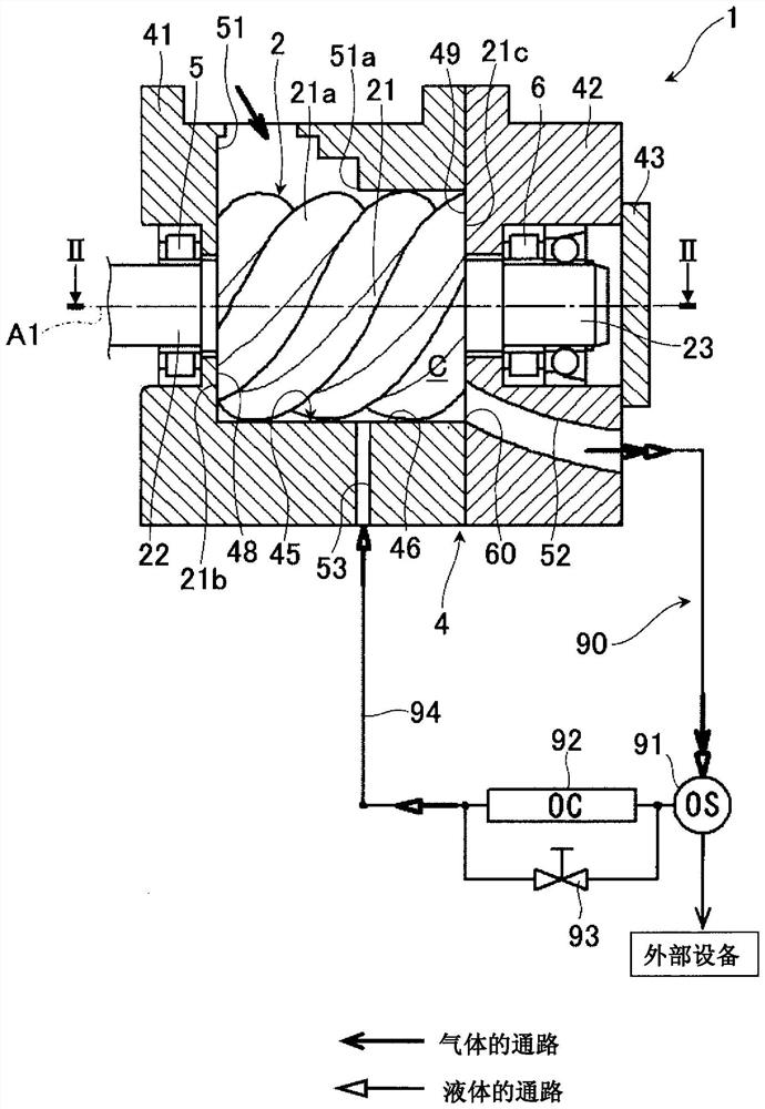
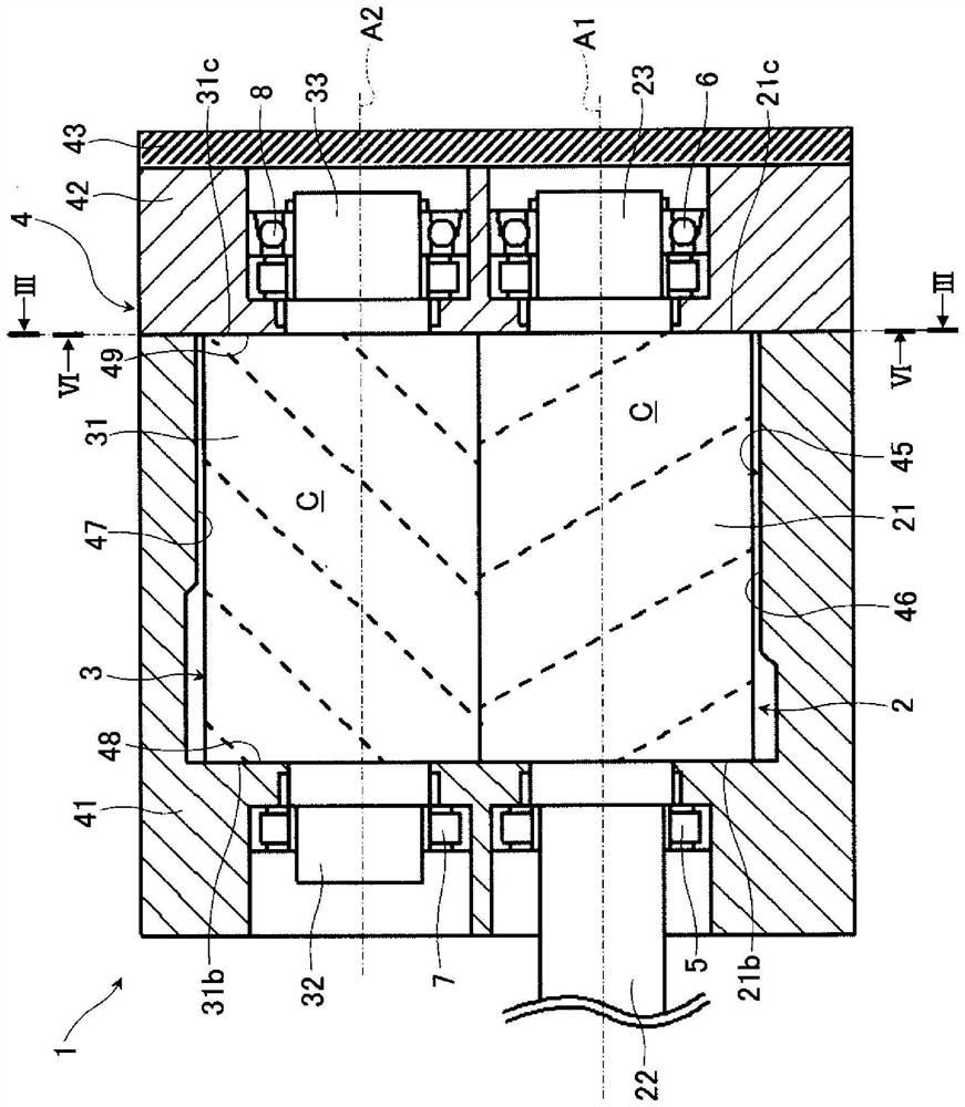
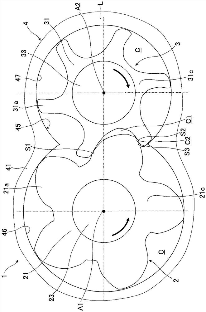
[0036] use Figure 1 and Figure 2 Describes the structure and action of the first embodiment of the liquid-supply screw compressor. Figure 1 is a cross-sectional view of a liquid supply screw compressor representing a first embodiment of the present invention and a system diagram illustrating the external path of the liquid supply screw compressor. Figure 2 is from Figure 1 The II-II shown looks at the cross-sectional view of the first embodiment of the present invention in the liquid-supply screw compressor. Figure 2 is from Figure 1 The II-II shown looks at the cross-sectional view of the first embodiment of the present invention in the liquid-supply screw compressor. Figure 1 and Figure 2 In the middle, the left side is the suction side of the liquid-supply screw compressor, and the right side is the discharge side. Figure 2 , the dotted line shows that it appears on the bottom side of the yang and yin rotors ( Figure 1 The top line of the tooth on the lower side).

[0037] Fig...

no. 2 approach

[0094] Subsequently, for the second embodiment of the liquid supply screw compressor is used Figure 15 Example description. Figure 15 is an enlarged view of the axial discharge outlet in a liquid-supply screw compressor representing a second embodiment of the present invention. Other than that Figure 15 Medium, and Figures 1 to 14 The part of the same symbol shown in the symbol is the same part, so its detailed description is omitted.

[0095] Figure 15 The second embodiment shown in the liquid supply screw compressor and the first embodiment of the liquid supply screw compressor (reference Figure 7 The difference is that a structure is adopted so that the axial discharge outlet 60A of the second slot 63A extends only from the first slot 62 to the midway position of the first contour line 71. Specifically, the second slot portion 63A is the same as the first embodiment, one side end is connected to the connection position 64 of the first slot portion 62. On the other hand, the ot...


PUM


Abstract

The invention provides a liquid supply type screw compressor. A discharge port (60) of a screw compressor is configured from: a first opening (61) having a profile capable of cutting off communication with a second working chamber (C2) of a suction stroke that opens only in the axial direction; a second opening connected to the first opening; and a third opening connected to the first opening and the second opening. The contour of the first opening portion includes a first contour line (71) forming one of a pair of side edges of a tongue-shaped protruding portion (50) capable of closing the second working chamber and extending towards a certain base point (P), a second contour line (72) forming the other of the pair of side edges of the protruding portion, and a third contour line (73) extending towards the base point along the tooth root circle of the female rotor. And a second connecting line (82) connecting the first contour line and the third contour line. The second opening portion is a first groove portion (62) that opens toward the first opening portion at the second connecting line and extends toward the reference line (L). The third opening portion is a second groove portion (63) that opens to the first groove portion and extends in an open state along the first contour line.

Description

Technical field [0001] The present invention relates to a liquid supply screw compressor for supplying liquids such as oil or water to the studio, in more detail, to a liquid-containing compressed gas containing a liquid in the studio through the discharge outlet of the liquid supply screw compressor. Background [0002] Screw compressors have been widely used as air compressors and compressors for refrigeration and air conditioning, and in recent years, there has been a strong demand for energy conservation. Therefore, in screw compressors, it is increasingly important to achieve high energy conversion efficiency. [0003] The screw compressor comprises a pair of screw rotors with a plurality of spiral teeth (cogging grooves), and a shell that holds two screw rotors in a state of meshing with each other, the volume of the studio formed by the two screw rotors and the inner wall of the housing increases or decreases with the rotation of the two screw rotors, thereby inhaling gas ...

Claims


Application Information

Patent Timeline
Patent Type & Authority Applications(China)
IPC IPC(8): F04C18/16F04C29/00
CPCF04C18/16F04C29/00F04C29/12F01C21/108F04C2250/102F04C18/20
Inventor 土屋豪千叶纮太郎高野正彦頼金茂幸森田谦次
Owner HITACHI IND EQUIP SYST CO LTD
Learn More