Grinding device for hydraulic valve element

A technology of hydraulic valves and grinding discs, which is applied in the direction of grinding drive devices, grinding/polishing safety devices, grinding machines, etc., to achieve the effect of improving surface utilization

Inactive Publication Date: 2022-06-10
王作申
View PDF0 Cites 1 Cited by
  • Summary
  • Abstract
  • Description
  • Claims
  • Application Information

AI Technical Summary

Problems solved by technology

[0004] Aiming at the deficiencies in the use of the existing valve core grinding device proposed in the background technology, the present invention provides a hydraulic valve core grinding device, which has The advantages of mechanical grinding and good grinding effect solve the technical problems raised in the above background technology

Method used


Image

  • Grinding device for hydraulic valve element
  • Grinding device for hydraulic valve element
  • Grinding device for hydraulic valve element

Examples


Embodiment Construction

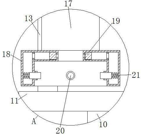
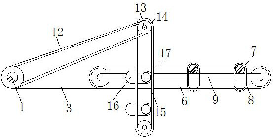
[0019] see image 3 , Figure 4 , the straight line where the rack belt II6 is located is perpendicular to the straight line where the rack belt IV15 is located, and when the rack belt IV15 is parallel to the rack belt II6, the two ends of the rack belt II6 protrude from the two ends of the rack belt IV15, and pass The strip II6 controls the lateral movement of the fixed block 7 and the slider 8, and then drives the fixed slider 16 and the movable rod 17 to move through the rotation of the rack belt IV15, and the straight line where the rack belt IV15 is located and the straight line where the rack belt II6 is located are perpendicular to each other, that is, the rack belt IV15 and the rack belt II6 move at the same time, so that the movement of the movable rod 17 and the slider 8 is carried out simultaneously, so that when the tray 10 follows the movement of the slider 8, the bottom of the fixed box 18 The movement trajectory of the fixed hydraulic spool on the surface of th...


PUM


Abstract

The invention relates to the technical field of valve element grinding, and discloses a hydraulic valve element grinding device which comprises a power shaft, the outer side of the power shaft is fixedly connected with a driving wheel, the outer side of the driving wheel is meshed with a rack belt I, the other end of the rack belt I is meshed with a driven wheel, and the middle of the driven wheel is movably connected with a fixing rod. The outer side of the driven wheel is engaged with a rack belt II located above the rack belt I. The motion path of the sliding block is divided into two mutually perpendicular motions in two directions, the fixed sliding block connected with the rack belt IV drives the movable rod to move in the vertical direction, then the fixed block connected with the rack belt II drives the sliding block to move in the transverse direction, and the rotation speed of the power shaft and the diameter of the driving wheel are adjusted. The movement path of the hydraulic valve element fixed by the fixing box at the top end of the grinding disc is in the shape of a grinding track, so that a sliding block-shaped grinding mode is achieved through mechanical movement, and the surface of the hydraulic valve element is free of grinding scratches and smoother.

Description

technical field [0001] The invention relates to the technical field of valve core grinding, in particular to a hydraulic valve core grinding device. Background technique [0002] The hydraulic spool is the main part of the hydraulic valve. During the processing of the hydraulic spool, the surface of the hydraulic spool is uneven or the surface is not smooth enough for a long time, resulting in a decrease in the sealing degree of the hydraulic spool. The traditional best method is to pass 8-shaped grinding by manual operation can make the surface of the hydraulic valve core free from scratches and microscopic scratches in the grinding direction. [0003] The traditional grinding device clamps the rod of the hydraulic spool and manually grinds the 8-shaped track, which can avoid scratches on the surface of the hydraulic spool. The consumption of components is large, which affects the grinding effect of the hydraulic valve core. Contents of the invention [0004] Aiming at ...

Claims


Application Information

Patent Timeline
Patent Type & Authority Applications(China)
IPC IPC(8): B24B15/04B24B41/00B24B41/06B24B55/00B24B47/04
CPCB24B15/04B24B41/005B24B41/06B24B55/00B24B47/04
Inventor 王作申
Owner 王作申
Why Eureka
Try Eureka