Anti-load self-protection type recovery training nursing device for orthopedic sick old people
A nursing device and technology for the elderly, which is applied in the direction of adjusting coordination training equipment, adjusting cardiovascular system training equipment, physical therapy, etc., and can solve problems such as increased training load resistance, large load resistance, and increased patient training load. Accelerate the speed of blood circulation, improve practicality, and improve the effect of recovery speed
- Summary
- Abstract
- Description
- Claims
- Application Information
AI Technical Summary
Problems solved by technology
Method used
Image
Examples
Embodiment 2
[0052] Embodiment 2, this embodiment is based on the above-mentioned embodiment, and the user performs active training through the device.
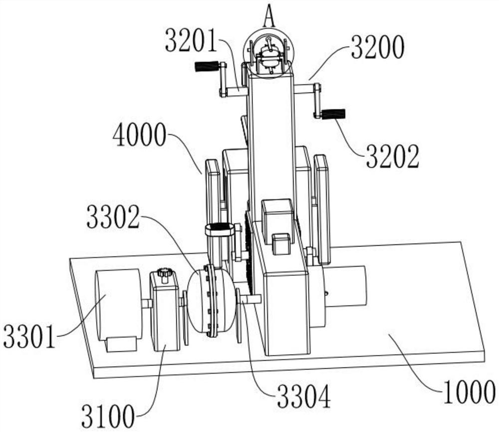
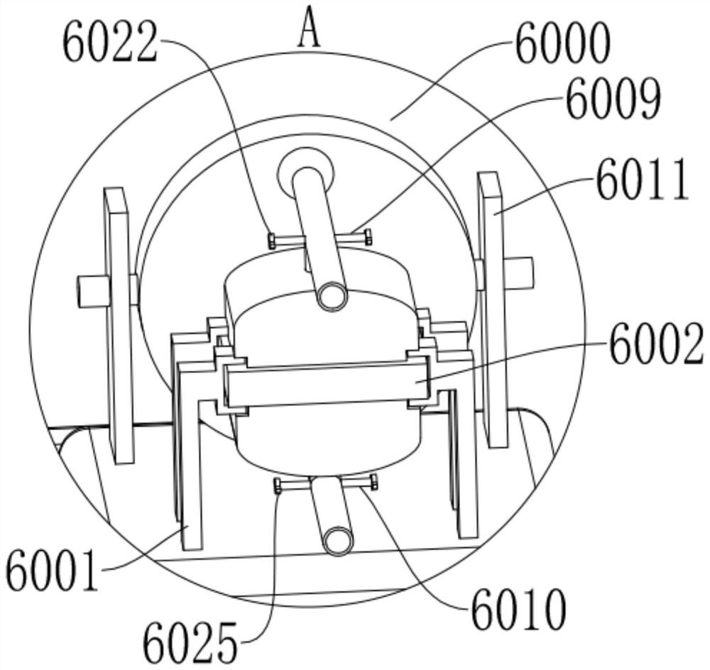
[0053] Specifically, the user rotates the fixed adjustment knob 3103, the fixed adjustment knob 3103 drives the fixed active two-way screw 3102 to rotate, the fixed active two-way screw 3102 drives the fixed active transmission wheel 3105 to rotate, and the fixed active transmission wheel 3105 is driven by the fixed transmission belt 3107 The fixed driven two-way screw 3106 is driven to rotate, so that the fixed and driven two-way screw 3104 and the fixed and active two-way screw 3102 rotate synchronously. The clamping plates 3108 are close to each other, and the two sets of clamping plates 3108 drive the two sets of anti-skid protrusions 3109 to approach each other, and gradually press against the fixed connection shaft 3110, so that the fixed connection shaft 3110 changes from a rotatable state to a fixed state, and then drives the motor...
Embodiment 3
[0054] Embodiment 3, this embodiment is based on the above embodiment, after the patient feels tired during active training, the patient can use the device to perform passive training.
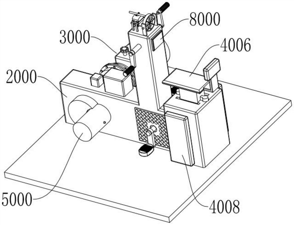
[0055]Specifically, the user activates the drive motor 3301 through the controller 8000, the drive motor 3301 drives the fixed connection shaft 3110 to rotate, the fixed connection shaft 3110 drives the power input shaft 3303 on the torque converter 3302 to rotate, and the power input shaft 3303 rotates through hydraulic force The transmission drives the power output shaft 3304 to rotate, the power output shaft 3304 drives the training driven shaft 3205 to rotate, the training driven shaft 3205 drives the training driven transmission wheel 3210 to rotate, and the training driven transmission wheel 3210 drives the training active transmission wheel through the training transmission belt 3211. 3209 rotates, the training active transmission wheel 3209 drives the training active shaft 3203 to rotat...
Embodiment 4
[0056] Embodiment 4, this embodiment is based on the above-mentioned embodiment, during training, the patient can use the temperature adjustment component according to the difference of the ambient temperature, so as to realize the training in the best state.
[0057] Specifically, during training, the training driven shaft 3205 can drive the power generation drive gear 5006 to rotate, the power generation drive gear 5006 drives the power generation driven gear 5007 to rotate, the power generation driven gear 5007 drives the power generation rotating shaft 5004 to rotate, and the power generation rotating shaft 5004 drives the permanent The magnet 5005 rotates in the generator casing 5002. Since the generator coil 5003 is fixedly arranged on the generator casing 5002, the permanent magnet 5005 rotates in the generator casing 5002, so that the magnetic field lines can be cut by the generator coil 5003, thereby Induced current is generated in the generator coil 5003, and the indu...
PUM
 Abstract
Description
Claims
Application Information
 - R&D
- Intellectual Property
- Life Sciences
- Materials
- Tech Scout
- Unparalleled Data Quality
- Higher Quality Content
- 60% Fewer Hallucinations
Browse by: Latest US Patents, China's latest patents, Technical Efficacy Thesaurus, Application Domain, Technology Topic, Popular Technical Reports.
© 2025 PatSnap. All rights reserved.Legal|Privacy policy|Modern Slavery Act Transparency Statement|Sitemap|About US| Contact US: help@patsnap.com


