
Large-span factory building roof modular installation device and construction method

An installation device and modular technology, which is applied in the field of modular installation devices on the roof of large-span factory buildings, can solve the problems of high construction cost, slow construction speed, and danger of high-altitude operations, and achieve the goal of reducing construction cost, reducing consumption, and shortening the construction period. Effect

Pending Publication Date: 2022-06-21
杭州广亦建设工程有限公司
View PDF0 Cites 0 Cited by
  • Summary
  • Abstract
  • Description
  • Claims
  • Application Information

AI Technical Summary

Problems solved by technology

[0007] The purpose of the present invention is to provide a large-span factory roof modular installation device and construction method to solve the technical problems of slow construction speed, high-altitude operation danger and high construction cost existing in the prior art for large-span factory roof construction methods

Method used


Image

  • Large-span factory building roof modular installation device and construction method
  • Large-span factory building roof modular installation device and construction method
  • Large-span factory building roof modular installation device and construction method

Examples


Embodiment 1

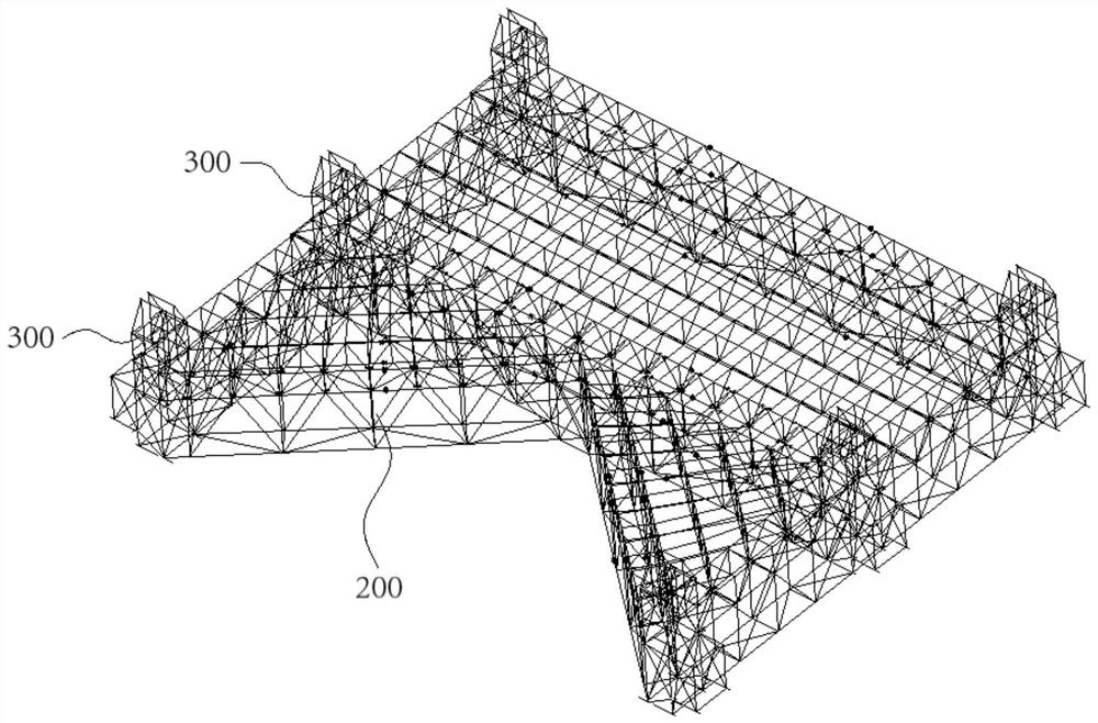
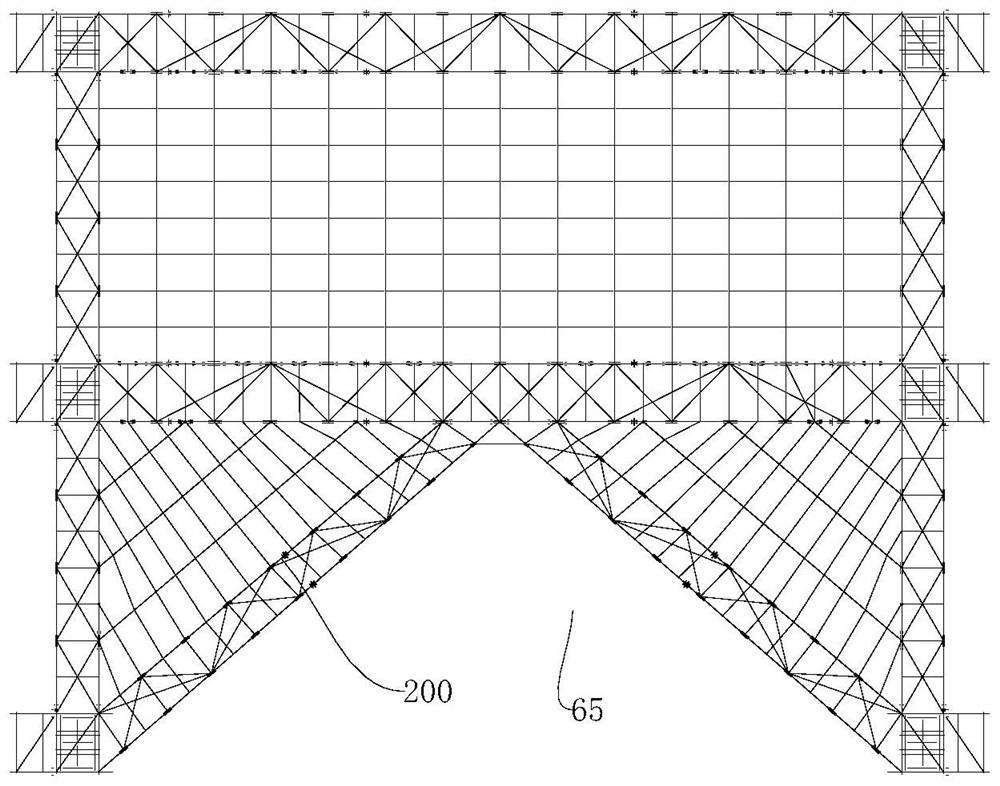
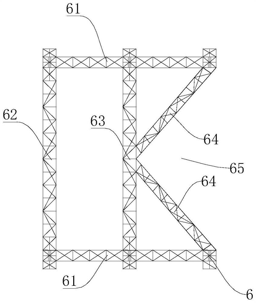
[0049] like figure 1 As shown, the present invention provides a large-span factory floor modular installation device, including a K-type tire frame 200, a roof truss limiting device 300 and a roof truss jacking device 400, wherein the K-type tire frame 200 is located in the upper part of the factory building and can be installed along the The length direction of the workshop reciprocates sliding; the K-type tire frame 200 is used to provide an operating platform for the assembly of the roof structure 21, and at the same time, it is used to carry the roof structure and slide it to the installation position in the horizontal direction. The roof truss limiting devices 300 are correspondingly arranged at the nodes of the K-type tire frames 200 to form a limit on the roof structure 21; the roof truss limiting device 300 is used to limit the roof structure to ensure that the Stability of roof structures during sliding. The roof truss jacking device 400 is arranged in the roof truss...

Embodiment 2

[0058] This embodiment provides a method for construction using the large-span factory floor modular installation device of Embodiment 1, including the following steps:

[0059] Step 1: Assemble the K-type tire frame 200, and lift the K-type tire frame 200 to the design elevation.

[0060] Specifically: assemble the K-type tire frame 200 in situ on the ground; use the standard section support frame 1 and the jacking assembly of the tire frame jacking device 700 to lift the K-type tire frame to the design track level; wherein, the temporary support adopts the prefabricated type Turn around the support frame, after the jacking device rises for one stroke, install a temporary support standard section until the tire frame is jacked up to the design track level, then install the sliding track and the driving end beam, and unload the K-type tire frame 200 to the sliding on track.

[0061] Step 2: Use a crane to hoist the roof components to the steel plate of the K-type tire frame f...


PUM


Abstract

The invention provides a large-span factory building roof modular installation device and a construction method. The problems that an existing construction method of a large-span factory building roof is low in construction speed, high-altitude operation is dangerous, and the construction cost is high are solved. The device comprises a K-shaped jig frame, a roof truss limiting device and a roof truss jacking device. The K-shaped jig frame is located on the upper portion of a plant and can slide in the length direction of the plant in a reciprocating mode. The roof truss limiting devices are arranged at the K-shaped jig frame joints in a pairwise corresponding mode so as to limit the roof structure. The roof truss jacking device is arranged in the roof truss limiting device, and the action end of the roof truss jacking device acts on the roof structure; when the roof structure is installed, after the K-shaped jig frame supports the roof structure to slide in place in the horizontal direction, the roof truss jacking device drives the roof structure to jack the roof structure to the installation position in the limiting space formed by the roof truss limiting device in the vertical direction. The modular installation requirement of large-span factory building roof installation is met, time is saved, and the construction period is shortened.

Description

technical field [0001] The invention relates to the technical field of building construction devices, in particular to a large-span factory floor modular installation device and a construction method. Background technique [0002] At present, for the more common large-span steelmaking workshops or stockyards, the workshops are characterized by large horizontal spans, regular longitudinal structures, and large lengths. They are equipped with a full-length crane beam system, and the roof structure is simple and unified. Or roof trusses, roof horizontal braces, sandalwood strips, braces and roof panels. [0003] However, the applicant found that the prior art has at least the following technical problems: At present, the roof structure construction of such structures generally adopts high-altitude splicing, or is installed in small pieces. Using the above method to install has the following disadvantages: [0004] 1. The construction speed is slow; [0005] 2. In the process...

Claims


Application Information

Patent Timeline
Patent Type & Authority Applications(China)
IPC IPC(8): E04G21/14E04G21/16E04B1/35
CPCE04G21/14E04G21/16E04G21/162E04B1/35
Inventor 王海龙王祖锋夏绍全
Owner 杭州广亦建设工程有限公司
Learn More