
Temperature compensation attenuator and design method thereof

A design method and technology of attenuators, which are applied to frequency-independent attenuators, amplifiers, and network improvement to reduce the influence of temperature changes, etc., can solve the problem of complex amplifier current structure, small operating frequency range, and small compensation dynamic range. and other problems, to achieve the effect of expanding the voltage adjustment range, wide operating temperature range, and high temperature compensation accuracy.

Pending Publication Date: 2022-06-21
NO 55 INST CHINA ELECTRONIC SCI & TECHNOLOGYGROUP CO LTD
View PDF0 Cites 0 Cited by
  • Summary
  • Abstract
  • Description
  • Claims
  • Application Information

AI Technical Summary

Problems solved by technology

Commonly used temperature compensation methods are as follows: 1. The op amp controls the voltage compensation, performs closed-loop feedback through the sampling signal at the output end, and compensates the gain at the input end; there are defects such as temperature offset, long response time, and high cost.
2. Bias circuit compensation, based on the temperature characteristics of diodes and transistors, controls the static operating point and bias voltage of transistors, etc., which will easily cause the amplifier current structure to be complicated and the operating frequency range to be small
3. The thermistor temperature compensation attenuator uses current to change the attenuation accordingly, which has the disadvantages of large device size, small compensation dynamic range, and difficulty in adapting to high-frequency applications.

Method used

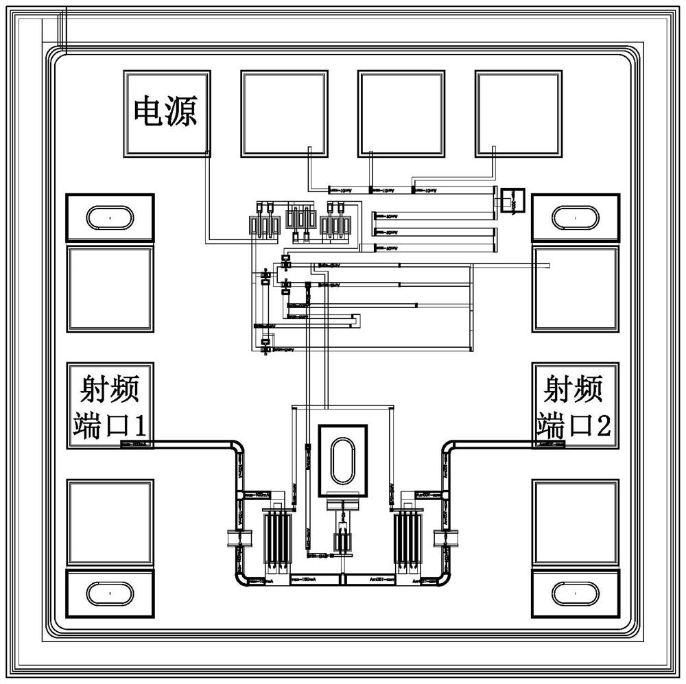
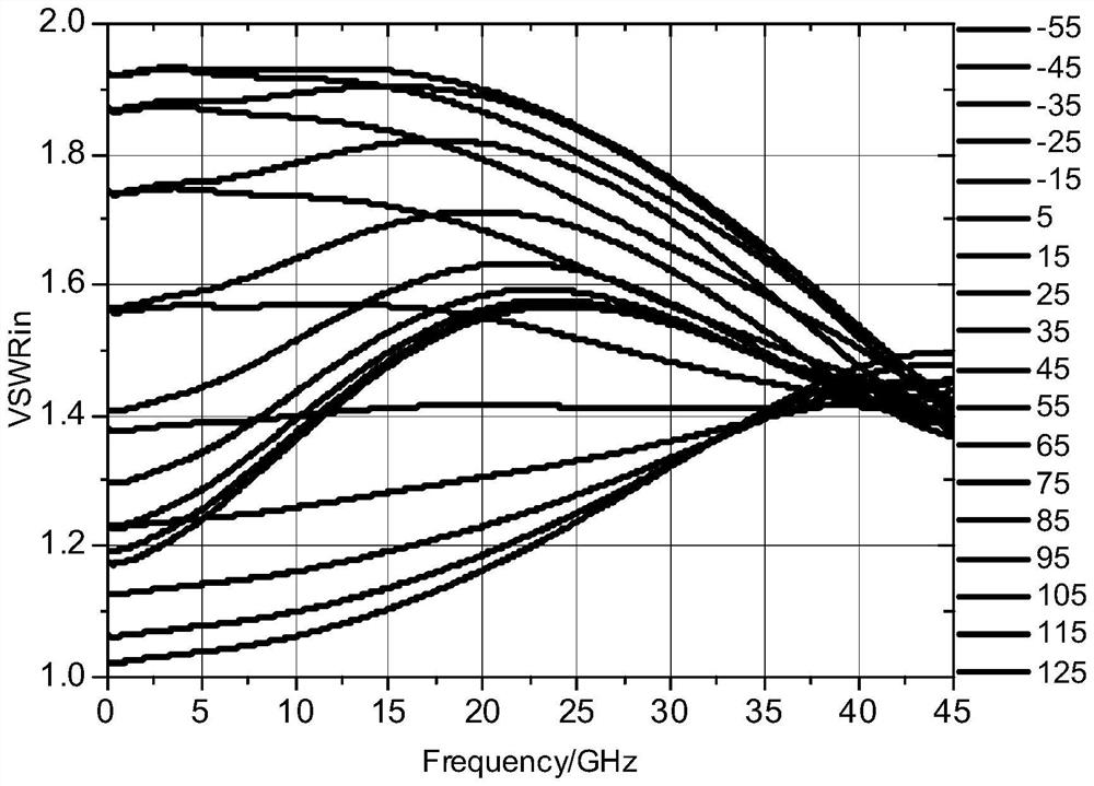

Image

  • Temperature compensation attenuator and design method thereof
  • Temperature compensation attenuator and design method thereof
  • Temperature compensation attenuator and design method thereof

Examples


Embodiment Construction

[0020] The present invention will be further described in detail below with reference to the accompanying drawings and specific embodiments.

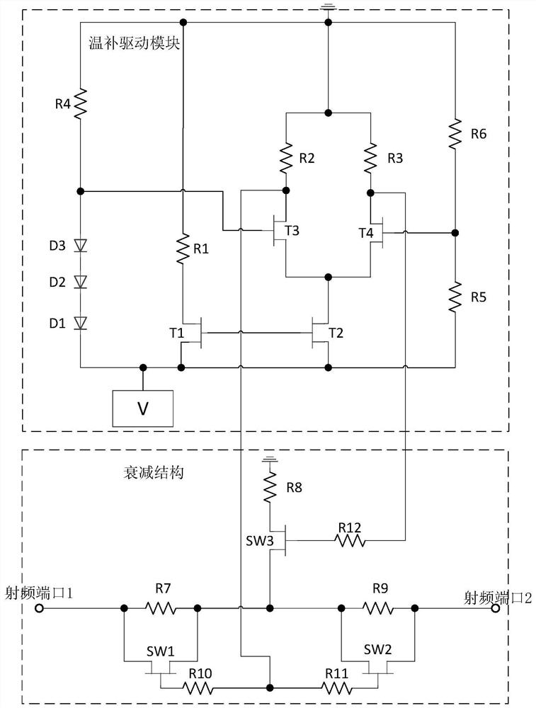
[0021] The invention discloses a temperature compensation attenuator circuit and a design method thereof. The temperature compensation attenuator includes a temperature compensation drive module and an attenuation structure circuit. The temperature compensation drive module adjusts the attenuation of the attenuation structure circuit according to the temperature compensation circuit and the differential network control voltage, and the attenuation structure circuit is connected between the radio frequency input port and the output port to realize the circuit attenuation compensation function.

[0022] Further, the temperature compensation drive module is composed of a temperature compensation circuit and a differential network. A temperature compensation circuit is formed by a diode and a resistor with temperature characteristics. The ...


PUM


Abstract

The invention discloses a temperature compensation attenuator and a design method thereof, relates to an attenuator device, and belongs to the field of radio frequency microwaves, and the temperature compensation attenuator comprises a temperature compensation driving module and an attenuation structure. Wherein the temperature compensation driving module adjusts the attenuation amount of the attenuation structure circuit according to the temperature compensation circuit and the differential network control voltage, and the attenuation structure circuit is connected between the input port and the output port to realize a circuit attenuation compensation function. The temperature compensation attenuator provided by the invention solves the problem of gain variation of an active device caused by temperature variation in a microwave / radio frequency channel, is wide in working frequency range, and is suitable for a large attenuation compensation range.

Description

technical field [0001] The invention belongs to the field of radio-frequency microwave attenuator devices of microelectronics and solid-state electronics, and particularly relates to a temperature-compensated attenuator and a design method thereof. Background technique [0002] As a control element in the microwave / RF channel, the temperature-compensated attenuator controls the signal amplitude and performs temperature compensation for the amplifier gain. It has requirements in terms of operating frequency band, insertion loss, response speed, and dynamic range of attenuation. The commonly used temperature compensation methods are as follows: 1. The op amp controls voltage compensation, and performs closed-loop feedback through the sampling signal at the output to compensate the gain at the input; there are defects such as temperature offset, long response time, and high cost. 2. Bias circuit compensation, based on the temperature characteristics of diodes and transistors, c...

Claims


Application Information

Patent Timeline
Patent Type & Authority Applications(China)
IPC IPC(8): H03H11/24H03H11/54H03F1/12
CPCH03H11/24H03H11/54H03F1/12
Inventor 邹文静潘晓枫王奇杨清愉郑诗敏凌显宝
Owner NO 55 INST CHINA ELECTRONIC SCI & TECHNOLOGYGROUP CO LTD
Learn More