Ceramic vessel

A technology of utensils and ceramics, applied in container cultivation, chemical instruments and methods, applications, etc., can solve the problems of observation, cleaning trouble, plants can not breathe oxygen, etc., to improve the utilization rate and ensure the effect of clean and tidy.

Pending Publication Date: 2022-06-24
李家燕
View PDF0 Cites 0 Cited by
  • Summary
  • Abstract
  • Description
  • Claims
  • Application Information

AI Technical Summary

Problems solved by technology

[0003] A flowerpot is a container for planting flowers made of ceramic materials. According to the size of the plants and flowers to be planted, different flowerpot sizes are produced; usually a through hole is set at the bottom of the flowerpot, and a through hole is installed below the through hole. Tray, this tray is specially used to catch the water leaking from the flower pot; however, the internal water level of the ceramic flower pot cannot be directly obs

Method used


Image

  • Ceramic vessel
  • Ceramic vessel
  • Ceramic vessel

Examples


Embodiment approach

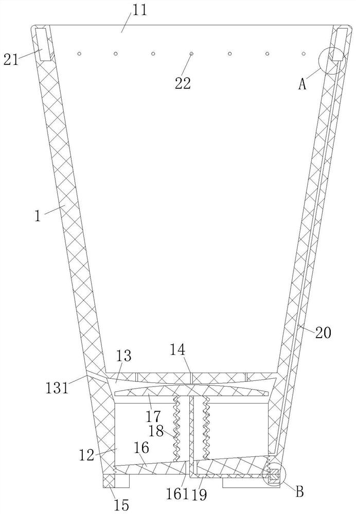
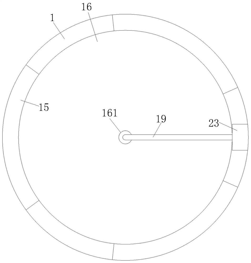
[0043] As a specific embodiment of the present invention, the lower end of the basin body 1 is provided with a support foot 15; the middle part of the basin bottom 16 is provided with an air outlet 161; the elastic member is an elastic bag 18; the driving unit is a pull rope 19; One end of the pull rope 19 is fixedly connected with the circular plate 17, and the other end is fixed to the bottom of the basin body 1 through the air outlet 161; the elastic bag 18 is sleeved on the place where the pull rope 19 is located. On one side of the water storage cavity 12, one end of the elastic bag 18 is fixedly connected with the circular plate 17, and the other end is fixedly connected with the basin bottom 16;

[0044] During work, when the plants in the pot body 1 need to be watered, the pull rope 19 is pulled, and the pull rope 19 drives the circular plate 17 to slide down along the side wall of the water storage cavity 12, and the water stored in the water storage cavity Squeezed b...

specific Embodiment approach

[0052] As a specific embodiment of the present invention, the upper end surface of the water guide groove 13 is an arc surface that protrudes from the edge to the middle;

[0053] When working, when the water source flows from the cultivation room 11 to the water guide trough 13 through the water outlet 14, the water will flow along the upper end face of the water guide trough 13, which is raised from the edge to the middle, from the periphery of the end face to the middle, and as it adheres to the water guide groove. 13 The accumulation of water droplets in the middle of the upper end surface is getting bigger and bigger, and will eventually drop on the upper end surface of the circular plate 17 under the influence of gravity, and finally roll down into the water storage cavity 12;

[0054] By setting the upper end surface of the water guide trough 13 as an arc surface that protrudes from the edge to the middle, compared with a flat surface, it is possible to avoid the situati...


PUM


Abstract

The invention relates to the technical field of ceramic vessels, in particular to a ceramic vessel which comprises a basin body. A cultivation chamber is formed in the pot body; an opening is formed in the upper part of the cultivation chamber; a water outlet hole is formed in the lower end face of the cultivation chamber; an air inlet hole is formed in the side wall of the pot body, and a water storage cavity is formed in the lower part of the pot body; the water storage cavity is arranged below the cultivation chamber; one end of the water outlet is communicated with the cultivation chamber, and the other end of the water outlet is communicated with the water storage cavity; one end of the air inlet is connected with the water storage cavity, and the other end of the air inlet is communicated with the outside of the pot body; according to the flowerpot, the first water storage cavity is formed below the cultivation chamber, so that excessive water for watering the cultivation chamber can flow into the first water storage cavity through the water outlet holes, meanwhile, the air inlet holes are formed in the side wall of the flowerpot body, air outside the flowerpot can enter the cultivation chamber, redundant water is prevented from submerging plant root systems, and it is guaranteed that the plant root systems can breathe normally; and normal growth of plants in the cultivation room is ensured.

Description

technical field [0001] The invention relates to the technical field of ceramic containers, in particular to a ceramic vessel. Background technique [0002] Ceramics is a general term for pottery and porcelain, and is a product fired from natural silicates such as clay as the main raw material; utensils refer to the general term for objects used to hold articles; and ceramic utensils are objects made of ceramic materials to hold articles , In daily life, it is mainly used for bowls, saucers, cups, plates, basins and other utensils; [0003] A flowerpot is a kind of utensil for planting flowers made of ceramic materials. Different sizes of flowerpots are produced according to the size of the plants and flowers. Usually, a through hole is set at the bottom of the flowerpot, and a through hole is installed below the through hole. Tray, this tray is specially used to catch the water leaking out of the flowerpot; however, the internal water level of the ceramic flowerpot cannot b...

Claims


Application Information

Patent Timeline
IPC IPC(8): A01G9/02A01G9/06A01G27/02B08B5/02
CPCA01G9/02A01G27/02A01G9/06B08B5/02
Inventor 李家燕彭圆
Owner 李家燕
Why Eureka
Try Eureka