Spine endoscope safety working sheath capable of rapidly converting perfusion pressure

A fast conversion, endoscope technology, applied in the field of medical devices, can solve the problems of increased operation difficulty, complicated operation, and no setting, etc., and achieve the effect of reducing the difficulty of operation operation, simple device structure, and small size difference.

Active Publication Date: 2022-06-24
ZHUHAI WEIERKANG BIOTECH
View PDF6 Cites 2 Cited by
  • Summary
  • Abstract
  • Description
  • Claims
  • Application Information

AI Technical Summary

Problems solved by technology

The traditional spinal mirror working sheath does not have the function of high-pressure perfusion. The high-pressure state generated by the perfusion pressure during the high-pressure perfusion of the spinal mirror will aggravate the pain of the patient. Continuous high pressure may cause nerve damage. In severe cases, it may cause dura mater rupture and stop the operation. Surgical risks brought about by continuous high pressure generally need to increase the sealing cap or replace the hand instrument to achieve the conversion between high pressure and low pressure. The operation is cumbersome and increases the difficulty of the operation.
The existing patent document CN201910726720.9 discloses a high-pressure perfusion surgical endoscope with a special-shaped outer working tube, which discloses the function of high-pressure filling, but does not have a structure that can realize high-low pressure rapid conversion to avoid continuous high pressure risks of surgery
Moreover, the disclosed working pipe sleeve structure and the corresponding water outlet channel structure are designed based on the outer working pipe with a ring-shaped (special-shaped) pipe cross-section, and are not suitable for the outer working pipe with an ordinary circular pipe cross-section.

Method used


Image

  • Spine endoscope safety working sheath capable of rapidly converting perfusion pressure
  • Spine endoscope safety working sheath capable of rapidly converting perfusion pressure
  • Spine endoscope safety working sheath capable of rapidly converting perfusion pressure

Examples


Embodiment 1

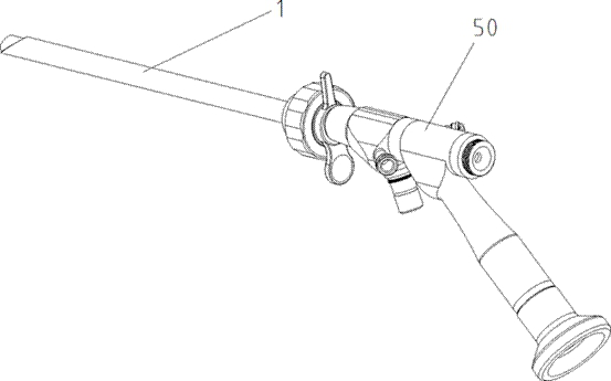
[0054] Further, as image 3 and 4 As shown, the conversion structure includes a valve 8, the valve 8 is cylindrical, the valve 8 is arranged in the middle of the conducting cylinder 2, and is located between the embedding groove and the end cover 4, The axial direction of the valve 8 is parallel to the axial direction of the sheath tube 1, and one side of the valve 8 is provided with a drainage hole 3 passing through the valve 8. The drainage hole 3 in the embodiment 1 is an oblong hole for drainage, so The axial direction of the drainage hole 3 is parallel to the axial direction of the sheath tube 1, and a small groove 6 is provided between the drainage hole 3 and the sheath tube embedding groove for discharging the flowing water from the water channel 103 into the casing. To the drain hole 3 , the end cover 4 is provided with a drain port 7 communicating with the drain hole 3 .

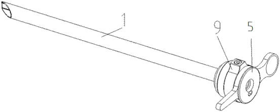
[0055] Further, the conversion control assembly also includes a stop knob 9, the stop knob 9 i...

Embodiment 2

[0060] like Figure 5-Figure 7 As shown, the conduction cylinder 2 in this embodiment is a multi-segment cylinder, the outer cylindrical surface of the uppermost segment is fixedly installed with the handle 5, and the cylindrical surface of the middle segment is provided with a plurality of drainage holes 3, such as Figure 7 As shown, a U-shaped chute 14 is arranged below the drainage hole 3, and the sheath tube 1 is installed in the last section; the water valve 13 is cylindrical as a whole, and one end is provided with a plurality of drainage ports 7, and the outer surface of the lower end of the drainage port 7 is provided with anti-skid The pin I15 is installed in the U-shaped groove on the outer surface of the conduction cylinder 2 and can move along the U-shaped chute 14; the spring 16 is located on the end face of the inner hole of the water valve 13, the spring cover 17 is used to fix the bottom of the spring, and the spring cover 17 is fixedly installed on one end of...

Embodiment 3

[0066] like Figure 8-Figure 10 As shown in the figure, a plurality of drainage holes 3 are arranged around the conducting cylinder 2 near the handle 5 , and a sliding groove 26 is provided on the side of the drainage hole 3 away from the handle 5 . A sliding pin 20 is provided, and the sliding pin 20 is slidably connected with the sliding groove 26; the conversion structure includes a knob 23, and the knob 23 is movably sleeved on the outer side of the conduction cylinder 2, and the knob 23 side The wall is provided with a plurality of drainage ports 7 communicating with the drainage holes 3 ; the inner wall of the knob 23 is also provided with a fixing groove 25 connected with the sliding pin 20 .

[0067] Further, a knob outer ring 22 is fixed on the outside of the knob 23 , and an elastic member 19 is provided between the knob outer ring 22 and the sliding pin. In this embodiment, the elastic member 19 is a spring. The two ends of the sliding groove 26 are provided with ...


PUM


Abstract

The invention discloses a spinal endoscope safety working sheath capable of quickly switching perfusion pressure, which comprises a sheath tube and a switching control assembly, and one end of the sheath tube is embedded into the switching control assembly; the sheath tube comprises a water channel and a working tube channel I; the working tube channel I is used for containing an endoscope outer working tube, the switching control assembly comprises a conduction column body, a sheath tube embedding groove is formed in one end of the conduction column body, a sheath tube is embedded into the sheath tube embedding groove, a drainage hole is formed in the middle of the conduction column body, and a switching structure used for controlling sealing or conduction of the drainage hole is arranged on the conduction column body. A working pipe channel II communicated with the working pipe channel I penetrates through the conduction column body, and a handle is arranged on the outer side of the end portion of the other end of the conduction column body. A switching structure is arranged on the working sheath handle, a doctor can freely select and rapidly switch the opening/closing state of a working sheath water channel according to clinical adaptation disease requirements in an operation, namely the high-pressure/low-pressure state generated by perfusion pressure in the operation, surgical instruments do not need to be additionally added or replaced, and the surgical operation difficulty is reduced.

Description

technical field [0001] The invention relates to the technical field of medical devices, in particular to a spinal endoscope safety working sheath capable of rapidly converting perfusion pressure. Background technique [0002] In clinical operations, it is usually necessary to use a working sheath to provide an instrument channel for medical instruments, and the working sheath is an indispensable auxiliary instrument in endoscopic surgery. The traditional spinal endoscopic working sheath does not have the function of high pressure perfusion. The high pressure state generated by the perfusion pressure during the high pressure perfusion of the spinal endoscope will aggravate the pain of the patient. Continued high pressure has the risk of nerve damage. In severe cases, the dura may rupture and the operation will be terminated. The surgical risk brought by continuous high pressure generally requires adding a sealing cap or replacing hand instruments to realize the conversion bet...

Claims


Application Information

Patent Timeline
Patent Type & Authority Applications(China)
IPC IPC(8): A61B17/00A61B90/00
CPCA61B17/00234A61B90/08A61B2017/00296A61B2017/0034A61B2017/00238
Inventor 胡善云吕劲贤李小雪
Owner ZHUHAI WEIERKANG BIOTECH
Why Eureka
Try Eureka