
Dynamic vibration absorber for vibration reduction of rotor

A dynamic vibration absorber and vibration absorber technology, applied in the functional characteristics of spring/shock absorber, vibration suppression adjustment, spring/shock absorber, etc., can solve the working conditions of fans, water pump motors, steam turbine generator sets, and large rotating machinery. Changes, rotor manufacturing errors and other problems, to achieve the effect of compact structure, long-term reliable operation, and stable damping

Pending Publication Date: 2022-06-24
HEFEI UNIV OF TECH
View PDF0 Cites 0 Cited by
  • Summary
  • Abstract
  • Description
  • Claims
  • Application Information

AI Technical Summary

Problems solved by technology

Large-scale rotating machinery has variable working conditions and complex vibration forms, which can easily lead to vibration problems in the rotor system
At the same time, rotor manufacturing errors and uneven wear during service will cause the unbalanced response of the rotor. Unbalanced rotors in operation are inevitable, especially for high-speed rotary equipment, where rotor unbalance is the main exciting force, such as fans and water pumps. Unbalanced motors, turbogenerators, etc. will cause damage to other parts of the equipment, such as bearings, motors, gears, etc.
With the continuous improvement of the performance requirements of the rotor, the vibration problem of the rotor has become increasingly prominent, which has become a bottleneck problem restricting the further development of related rotating machinery. The rotor system often works under extremely harsh conditions such as high temperature, high pressure, and high speed. It needs to be able to work reliably in harsh environments for a long time, so rotor vibration reduction for harsh working environments is urgently needed, and no related technology has been disclosed so far

Method used


Image

  • Dynamic vibration absorber for vibration reduction of rotor
  • Dynamic vibration absorber for vibration reduction of rotor
  • Dynamic vibration absorber for vibration reduction of rotor

Examples


Embodiment Construction

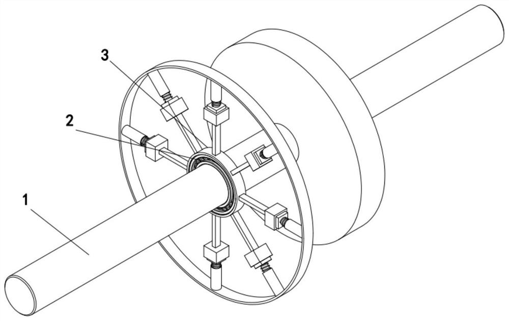
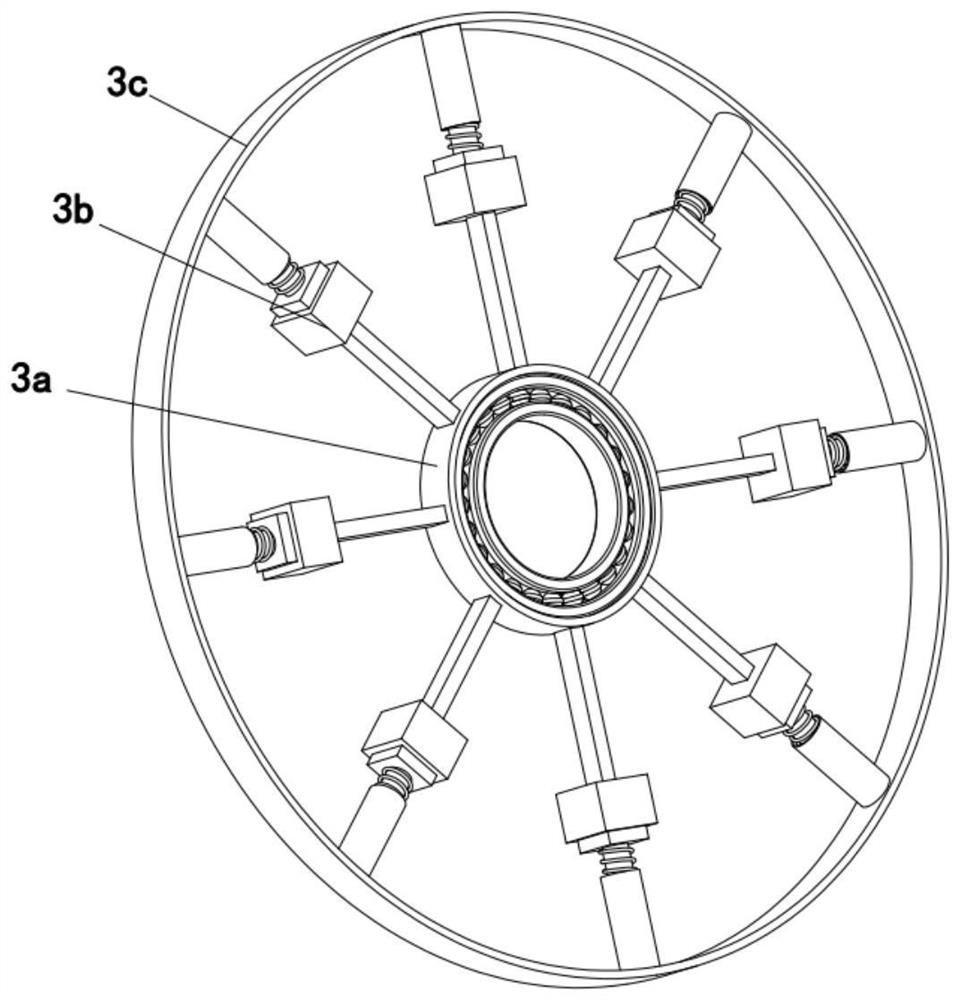
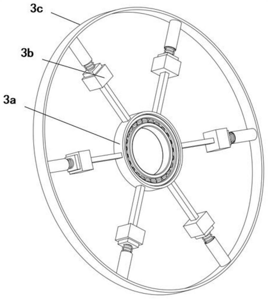
[0052] see figure 1 , figure 2 and Figure 5 In this embodiment, the dynamic vibration absorber 3 for rotor vibration reduction has an inner ring 3a and an outer ring 3c, n dry friction damping vibration absorbers 3b are arranged between the inner ring 3a and the outer ring 3c, and n dry friction damping vibration absorbers 3b Evenly distributed along the circumferential direction; a cantilever beam type resonator 3b.1 is set in the dry friction damping absorber 3b, the arm end of the resonator 3b.1 is connected to the inner ring 3a, and the vibrator end of the resonator 3b.1 is connected to the pressure rod 3b.2 offset each other, the rod end of the compression rod 3b.2 is fitted with the spring 3b.3, the spring 3b.3 is placed in the spring sleeve, the spring sleeve is connected with the outer ring 3c, the spring 3b.3 is between the harmonic oscillator 3b.1 and the pressure The rod 3b.2 provides positive pressure; the dynamic vibration absorber 3 is fixedly connected with ...


PUM


Abstract

According to the dynamic vibration absorber, a plurality of dry friction damping vibration absorbers are evenly distributed between an inner ring and an outer ring in the circumferential direction, the dynamic vibration absorber is fixedly connected with a machine shell through the outer ring, and the inner ring is installed on a rotor through a bearing, so that the dynamic vibration absorber does not rotate along with the rotor in the running process of the rotor; the inherent frequency of cantilever beam type harmonic oscillators in the dry friction damping vibration absorber is set to be close to the vibration frequency corresponding to the position where the rotor passes the critical rotating speed, so that when the rotor passes the critical rotating speed, the cantilever beam type harmonic oscillators are used for absorbing vibration energy of the rotor, and the cantilever beam type harmonic oscillators dissipate the vibration energy through dry friction; therefore, the purpose of reducing the vibration amplitude when the rotor passes through the critical rotating speed is achieved, and the vibration amplitude when the rotor system passes through the critical rotating speed can be remarkably reduced by optimizing the structural parameters of the dynamic vibration absorber.

Description

technical field [0001] The invention relates to the field of structural vibration control, and more specifically relates to a dynamic vibration absorber for rotor vibration reduction. Background technique [0002] Rotating machinery is an important equipment widely used in petrochemical, steel, electric power, aviation, aerospace and other national economic lifeline industries. Once these important equipment fail due to unplanned downtime or major accidents, it will bring huge economic losses and harm to the society. The rotor is a key component of large rotating machinery such as aero-engines, large compressors, and steam turbines. With the continuous improvement of the industrial level, the requirements for the production capacity and production efficiency of the petroleum, chemical and electric power industries are getting higher and higher. More and more large-scale rotating machinery adopts a multi-span rotor series structure. The limitation of factors such as precisio...

Claims


Application Information

Patent Timeline
IPC IPC(8): F16F15/129
CPCF16F15/129F16F2228/06Y02T90/00
Inventor 王帅杨庚孙磊汪方潮毕传兴郑昌军
Owner HEFEI UNIV OF TECH
Learn More