
Transfer case assembly optimization design method, transfer case assembly and engineering vehicle

An optimized design, transfer case technology, applied in the field of transfer case assembly and engineering vehicles, can solve the problems of potential safety hazards, heavy transfer case assembly, etc., achieve better performance, avoid abnormal noise of the transmission shaft failure, the effect of improving dynamic performance

Pending Publication Date: 2022-06-24
ZOOMLION HEAVY IND CO LTD
View PDF0 Cites 0 Cited by
  • Summary
  • Abstract
  • Description
  • Claims
  • Application Information

AI Technical Summary

Problems solved by technology

[0003] The main purpose of the present invention is to propose a transfer case assembly optimization design method, transfer case assembly and engineering vehicle, aiming to solve the technical problems of heavy transfer case assembly and potential safety hazards in the prior art

Method used


Image

  • Transfer case assembly optimization design method, transfer case assembly and engineering vehicle
  • Transfer case assembly optimization design method, transfer case assembly and engineering vehicle
  • Transfer case assembly optimization design method, transfer case assembly and engineering vehicle

Examples


Embodiment Construction

[0046] The specific embodiments of the present invention will be described in detail below with reference to the accompanying drawings. It should be understood that the specific embodiments described herein are only used to illustrate and explain the present invention, but not to limit the present invention.

[0047] The optimal design method of the transfer case assembly according to the present invention will be described below with reference to the accompanying drawings.

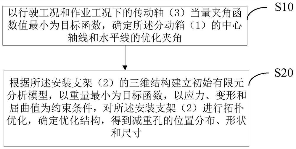
[0048] In an embodiment of the present invention, an optimal design method 100 for a transfer case assembly is provided, wherein the transfer case assembly 100 includes a mounting bracket 2 and a transfer case 1 mounted on the mounting bracket 2, so The two sides of the transfer case 1 are connected to one end of the transmission shaft 3 through the transmission universal joint 4, and the other end of the transmission shaft 3 is respectively connected to the gearbox 200 and the drive rear axle 300 through...


PUM

PropertyMeasurementUnit
Stress valueaaaaaaaaaa

Abstract

The invention provides a transfer case assembly optimization design method, a transfer case assembly and an engineering vehicle, the two sides of a transfer case are connected with one end of a transmission shaft through a transmission universal joint, and the other end of the transmission shaft is connected with a gearbox and a driving rear axle through two output universal joints respectively; performing equivalent included angle optimization by taking the minimum equivalent included angle function value of the transmission shaft under the driving working condition and the operation working condition as a target function, and determining an optimized included angle between the central axis of the transfer case and the horizontal line; and establishing an initial finite element analysis model according to the three-dimensional structure of the mounting bracket, taking the minimum weight as an objective function, taking stress, deformation and buckling values as constraint conditions, carrying out topological optimization on the mounting bracket, determining an optimized structure, and obtaining the position distribution, shape and size of the lightening holes. The optimization of the equivalent included angle under the driving working condition and the operation working condition is matched with the topological optimization of the mounting bracket, so that the inter-shaft included angle of the transmission shaft system is reduced, the abnormal sound fault of the transmission shaft system is avoided, and meanwhile, the light weight of the transfer case assembly can be realized.

Description

technical field [0001] The invention belongs to the technical field of vehicle manufacturing, and in particular relates to an optimal design method for a transfer case assembly, a transfer case assembly and an engineering vehicle. Background technique [0002] On the concrete pump truck, the transfer case assembly is one of the most core components in its transmission system. Its main function is to act as a switching device for the driving and working conditions of the vehicle. It is usually installed in the gearbox of the chassis and driving the rear axle. In between, it is fixed on the vehicle chassis through the mounting frame. Because the transfer case itself is heavy and the force is relatively complex, the existing solutions usually tend to be conservative in the structural design of the transfer case mounting frame, which is heavy, expensive and expensive. It is not conducive to the compliance requirements of the weight of the whole machine, and the transfer case of ...

Claims


Application Information

Patent Timeline
IPC IPC(8): G06F30/17G06F30/15G06F30/23G06F30/18G06F111/04G06F111/06G06F119/14
CPCG06F30/17G06F30/15G06F30/23G06F30/18G06F2111/04G06F2119/14G06F2111/06
Inventor 吴成平谢新鹏肖立波吴德志吴瀚晖
Owner ZOOMLION HEAVY IND CO LTD
Learn More