Broadband high-gain double-ridge horn antenna with loaded dielectric lens

A dielectric lens and high-gain technology, which is applied to antennas, waveguide horns, antenna components, etc., to improve engineering application prospects, facilitate engineering implementation and use, and improve the effect of improvement

Pending Publication Date: 2022-06-24
CHENGDU AIRCRAFT INDUSTRY GROUP
View PDF4 Cites 0 Cited by
  • Summary
  • Abstract
  • Description
  • Claims
  • Application Information

AI Technical Summary

Problems solved by technology

[0007] In order to overcome the problems and deficiencies in the above-mentioned prior art, this application proposes a wide-band high-gain double-ridge horn antenna loaded by a dielectric lens. Through a unique design of the antenna form and structure, the antenna frequency bandwidth and

Method used


Image

  • Broadband high-gain double-ridge horn antenna with loaded dielectric lens
  • Broadband high-gain double-ridge horn antenna with loaded dielectric lens
  • Broadband high-gain double-ridge horn antenna with loaded dielectric lens

Examples


Embodiment Construction

[0036] In order to make those skilled in the art better understand the technical solutions in the present application, the technical solutions for realizing the purpose of the invention of the present application will be further described below through several specific embodiments. It should be noted that the technical solutions claimed in the present application are Protocols include but are not limited to the following examples. Based on the embodiments in this application, all other embodiments obtained by those skilled in the art without creative work shall fall within the protection scope of this application.

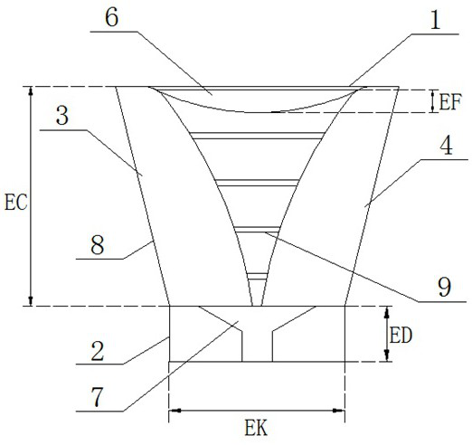
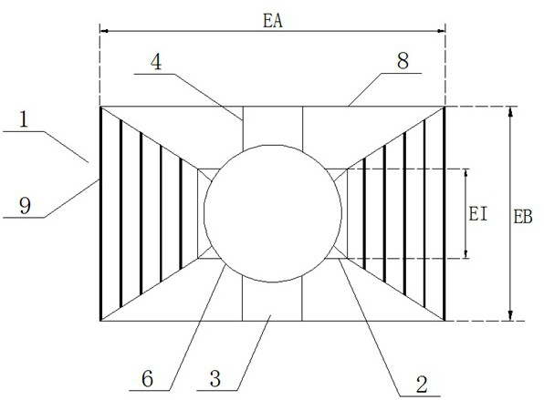
[0037]As we all know, the general 1-18GHz double-ridged waveguide horn antenna will have pattern fission above 12GHz. At these operating frequencies, the antenna pattern is not a main lobe, but is split into 4 lobes. This is because with the increase of the operating frequency, the higher-order modes are gradually excited, which makes the field distribution in the...


PUM

PropertyMeasurementUnit
Heightaaaaaaaaaa
Sizeaaaaaaaaaa
Sizeaaaaaaaaaa

Abstract

The broadband high-gain double-ridge horn antenna comprises a horn shell, a waveguide section, an upper ridge, a lower ridge, a coaxial feeder line and the dielectric lens, the bottom end of the horn shell is connected with the opening end of the waveguide section, the upper ridge and the lower ridge are fixed to the two opposite side walls of the horn shell respectively, the two ridges are the same in structure, and the coaxial feeder line is arranged on the waveguide section. A ridge line of the waveguide section comprises a straight line section and a curve section, the curve section adopts a cubic Bezier curve, the coordinate value of a control point of a tail end point of the curve is larger than that of a tail end point of the curve, the coaxial feeder line penetrates through the top end of the waveguide section and is connected with the upper ridge and the lower ridge, the dielectric lens is arranged at an opening in the top end of the loudspeaker shell, and the waveguide section is of a cubic structure. A wedge-shaped structure cavity which is integrally formed and manufactured is formed in the body; the dielectric lens is a convex-plane lens, and one side of the convex surface faces the inner cavity of the loudspeaker shell. Through unique design of the form and the structure of the antenna, the problems of the frequency bandwidth and the directional diagram bandwidth of the antenna are solved.

Description

technical field [0001] The present application relates to the technical field of communication antennas, in particular to the technical field of ultra-wideband antennas, and more particularly to a broadband high-gain double-ridged horn antenna loaded with a dielectric lens. Background technique [0002] Ultra-wideband antenna technology is a hot spot in antenna research at home and abroad. In military applications, it is mainly in radar monitoring, anti-stealth technology and electronic countermeasures, while in civilian applications, it is mainly in broadband communication, spread spectrum communication, ground penetrating radar, field monitoring and electromagnetic compatibility. UWB antennas generally refer to antennas with a ratio of the highest frequency to the lowest frequency of more than 10:1. In practical applications, in order to work normally in an ultra-wideband system, it is not only necessary to ensure that the impedance bandwidth of the antenna reaches a suff...

Claims


Application Information

Patent Timeline
IPC IPC(8): H01Q13/02H01Q1/42H01Q1/00H01Q15/08H01Q19/08
CPCH01Q13/0275H01Q1/42H01Q1/005H01Q19/08H01Q15/08
Inventor 张袁邓乐武王东俊张雷魏平袁雪蒂何谟谞周漪
Owner CHENGDU AIRCRAFT INDUSTRY GROUP
Why Eureka
Try Eureka