Single automatic wire welding equipment for LED (light-emitting diode) lamp strip

An LED light strip and automatic welding technology, which is applied in the field of wire welding machines, can solve the problems of affecting the welding effect, the position deviation of the light strip, and the poor effect of the LED light strip limit, so as to improve the fixing strength, increase the limit strength, and improve The effect of roughness

Pending Publication Date: 2022-06-28
瑞昌市瑞祥照明科技有限公司
View PDF0 Cites 0 Cited by
  • Summary
  • Abstract
  • Description
  • Claims
  • Application Information

AI Technical Summary

Problems solved by technology

[0004] The purpose of the present invention is to solve the disadvantages in the prior art that the traditional single semi-automatic wire welding machine has a poor limiting effect on the LED light strip, and the position of the light strip is easy to deviate during the welding process, which affects the welding effect, and proposes a LED light strip single automatic wire welding equipment

Method used


Image

  • Single automatic wire welding equipment for LED (light-emitting diode) lamp strip
  • Single automatic wire welding equipment for LED (light-emitting diode) lamp strip
  • Single automatic wire welding equipment for LED (light-emitting diode) lamp strip

Examples


Embodiment 1

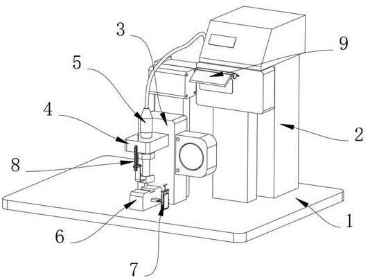
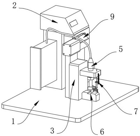
[0041] Example 1, as Figure 1-8 As shown, the present invention provides a single automatic wire bonding equipment for LED light strips, which includes a backing plate 1 and a limiting structure 7 . A workbench 3 is fixedly connected to the side, a support base 4 is installed on the surface of the workbench 3, a welded pipe 5 is installed in the support base 4, a base 6 is fixedly connected to the side of the backing plate 1 close to the welded pipe 5, and one side of the base 6 has a limit Positioning structure 7, the surface of the support base 4 is provided with a protective structure 8, and the surface of the manipulator 2 is provided with a shielding structure 9.

[0042] The specific settings and functions of the limiting structure 7 , the protective structure 8 and the shielding structure 9 will be described in detail below.

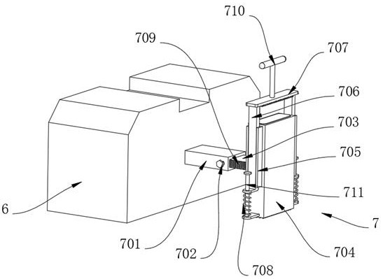
[0043] like image 3 and Figure 4 As shown, the limiting structure 7 includes a square tube 701, the square tube 701 is fixedly connected to...

Embodiment 2

[0049] Embodiment 2, on the basis of Embodiment 1, the shielding structure 9 includes a fixing frame 91, the fixing frame 91 is fixedly connected to the surface of the manipulator 2, the two arms of the fixing frame 91 are rotatably connected with a rotating rod 92, and the circle of the rotating rod 92 is rotatably connected. The arc surface is fixedly connected with a baffle plate 93, and one end of the rotating rod 92 is fixedly connected with a circular plate 94. The side of the circular plate 94 away from the rotating rod 92 is evenly provided with a number of card slots 95, and the fixing frame 91 is close to the side of the circular plate 94. A support frame 96 is fixedly connected, and a plug pin 97 is slidably inserted in the support frame 96. The size of the plug pin 97 is adapted to the size of the card slot 95 of the circular plate 94, so as to achieve the effect that the rotation angle of the baffle plate 93 can be quickly adjusted. 93 has the effect of blocking ex...


PUM


Abstract

The invention provides LED lamp strip single automatic wire welding equipment, and relates to the technical field of wire welding machines, the LED lamp strip single automatic wire welding equipment comprises a base plate and a limiting structure, the upper surface of the base plate is fixedly connected with a controller, the side, close to the controller, of the base plate is fixedly connected with a workbench, a supporting seat is installed on the surface of the workbench, a welding pipe is installed in the supporting seat, and the welding pipe is fixedly connected with the limiting structure. A base is fixedly connected to the side, close to the welded pipe, of the base plate, a limiting structure is arranged on one side of the base and comprises a square pipe, the square pipe is fixedly connected to the surface of the base, a pressing rod is inserted into the surface of the square pipe in a threaded mode, and a sliding plate is slidably connected to the inner wall of the square pipe. A rectangular block is fixedly connected to the end, away from the base, of the sliding plate, and sliding rails are fixedly connected to the two sides of the rectangular block. The single semi-automatic wire welding machine solves the problems that a traditional single semi-automatic wire welding machine is poor in limiting effect on an LED lamp strip, the position of the lamp strip is prone to deviation in the welding process, and the welding effect is affected.

Description

technical field [0001] The invention relates to the technical field of wire bonding machines, in particular to a single automatic wire bonding device for LED lamp strips. Background technique [0002] Wire bonding machine refers to the equipment for welding cables. In the production process of LED light strips, it is necessary to use wire bonding equipment to weld the cables of LED light strips. The more common wire bonding equipment is divided into single and semi-automatic wire bonding. equipment and single automatic wire bonding equipment. [0003] The traditional single and semi-automatic wire bonding machine has poor limiting effect on the LED light strip. When using the wire bonding machine, the operator needs to place the light strip on the wire bonding machine for welding. The position of the light strip is easy to deviate during the welding process, which affects the welding. Effect. SUMMARY OF THE INVENTION [0004] The purpose of the present invention is to so...

Claims


Application Information

Patent Timeline
IPC IPC(8): B23K37/00B23K37/04B23K101/36
CPCB23K37/00B23K37/0443B23K2101/36
Inventor 陈义财
Owner 瑞昌市瑞祥照明科技有限公司
Why Eureka
Try Eureka