Composite cutter service life monitoring system and method based on machine vision

A service life, machine vision technology, applied in the direction of manufacturing tools, measuring/indicating equipment, metal processing machinery parts, etc., can solve the problems of reducing the working efficiency of the device, increasing the error of monitoring work, and precise detection of wear and tear, so as to increase the practicality , Improve work efficiency and increase recognition efficiency

Pending Publication Date: 2022-06-28
SOUTHWEST JIAOTONG UNIV
View PDF6 Cites 0 Cited by
  • Summary
  • Abstract
  • Description
  • Claims
  • Application Information

AI Technical Summary

Problems solved by technology

[0006] 1. When the existing tool monitoring device uses electronic equipment such as a camera to monitor the tool, the camera is installed in a fixed position, so it can only shoot one side of the tool, and cannot recognize the tool in multiple directions and accurately measure the amount of wear. detection, and then it is easy to cause large errors in the detection data of the device, which reduces the feasibility of the device;
[0007] 2. The existing tool monitoring device can only analyze the conclusions through manual comparison of image data. Therefore, in the post-processing of device monitoring, the workload of the staff is also increased, and a large amount of data needs to be manually compared and analyzed. Not only It reduces the working efficiency of the device and increases the probability of errors in the monitoring work
[0008] 3. The existing tool monitoring device is not accurate enough for the monitoring accuracy and detection method of the tool. After the tool is worn, it will produce different degrees of wear in many different positions, and there are many ways such as cracks in the tool wear. Therefore, Traditional detection devices cannot effectively analyze and judge wear conditions accurately

Method used


Image

  • Composite cutter service life monitoring system and method based on machine vision
  • Composite cutter service life monitoring system and method based on machine vision
  • Composite cutter service life monitoring system and method based on machine vision

Examples


Embodiment 1

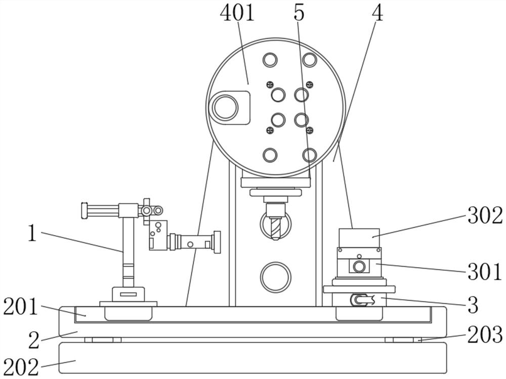
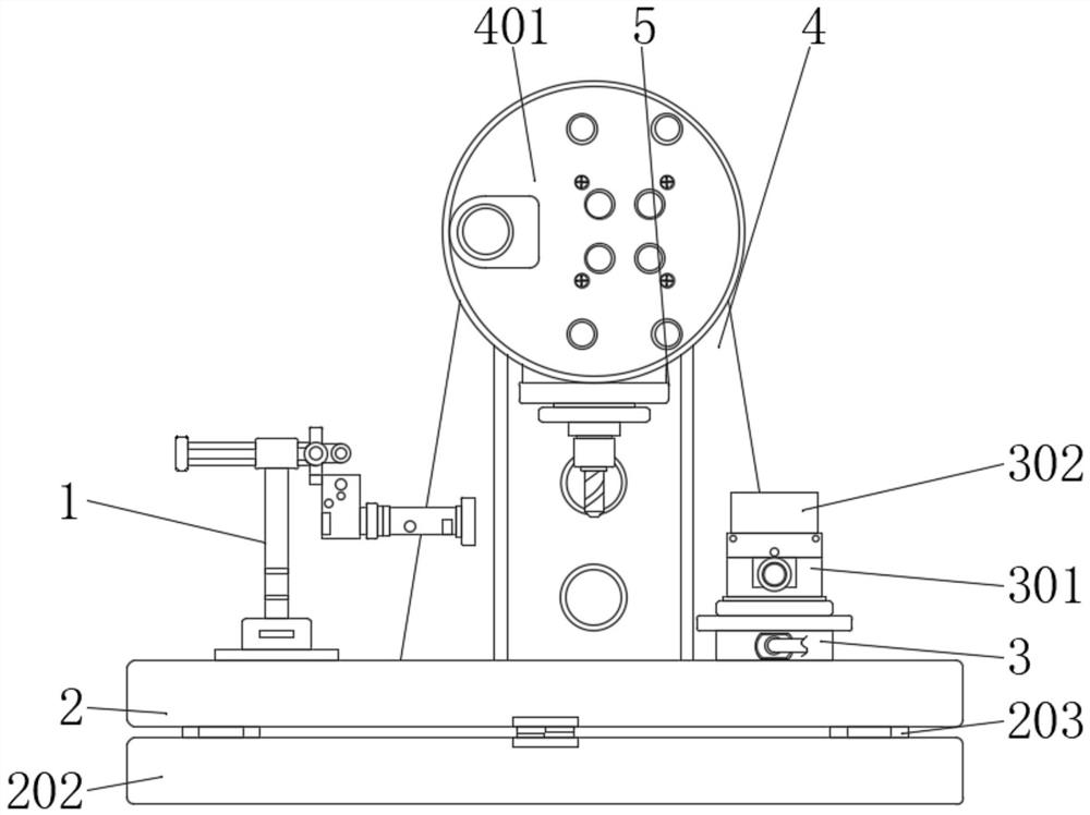
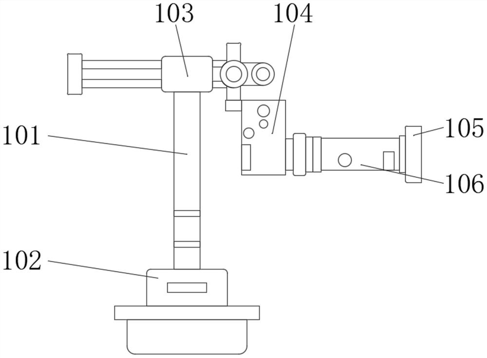
[0040] like Figure 1-5As shown, a machine vision-based composite tool service life monitoring system and method proposed by the present invention includes a monitoring component 1, a chute seat 2, a sliding seat 3 and a tool assembly 5, and a guide is provided inside the chute seat 2 Slot 201, a support seat 4 is installed on one side of the chute seat 2, a drive module 401 is installed on the top of the support seat 4, a tool assembly 5 is installed on the bottom side of the drive module 401, and a mounting plate is installed in the tool assembly 5 501, a knife seat 503 is installed on the bottom of the mounting plate 501, a sliding seat 3 is installed on the top side of the chute seat 2, and a monitoring component 1 is installed on the side of the top of the sliding groove seat 2 away from the sliding seat 3, and the monitoring component 1 A base 102 is installed, a rotating shaft 101 is installed on one side of the base 102 , a fixing base 103 is installed on the top of th...

Embodiment 2

[0053] like Figure 1-5 As shown in the figure, a system and method for monitoring the service life of a composite tool based on machine vision proposed by the present invention, compared with the first embodiment, the present embodiment further includes: a telecentric lens 106 is installed on one side of the camera 104, and the telecentric lens 106 is installed on one side. A ring light 105 is installed on one side of the central lens 106, a mounting shaft 203 is installed on both sides of the bottom of the sliding slot seat 2, and a mounting plate 202 is installed at the bottom of the mounting shaft 203, and a fixing plate 301 is installed on the top of the sliding seat 3, And a workpiece 302 is installed on the top of the fixing plate 301 , a motor is installed inside the drive module 401 , and the output end of the motor extends out of the bottom of the drive module 401 , and a tool bar 502 is installed at the bottom of the tool holder 503 , and the tool bar is A milling c...


PUM


Abstract

The invention relates to the technical field of cutter monitoring, in particular to a composite cutter service life monitoring system and method based on machine vision. According to the technical scheme, the device comprises a monitoring assembly, a sliding groove seat, a sliding seat and a cutter assembly, a supporting seat is installed on one side of the sliding groove seat, a driving module is installed at the top of the supporting seat, the sliding seat is installed on one side of the top of the sliding groove seat, and the monitoring assembly is installed on the side, away from the sliding seat, of the top of the sliding groove seat; the top of the rotating shaft is provided with a fixing seat, and one side of the bottom of the fixing seat is provided with a camera. According to the device, the rotating shaft is installed at the top of the base, the camera can be driven to move through the rotating shaft, the camera can collect images in all directions and angles of the cutter, and therefore the abrasion conditions of the composite cutter in different time periods and different directions can be monitored at the same time, and the practicability of the device can be improved.

Description

technical field [0001] The invention relates to the technical field of tool monitoring, in particular to a system and method for monitoring the service life of a composite tool based on machine vision. Background technique [0002] In the context of the continuous development of big data and the Internet of Things, the traditional machinery manufacturing industry is developing in the direction of intelligent informatization. More and more "smart factories" are applied in the field of industrial processing and manufacturing, and the degree of intelligence of CNC machine tools is also required. The higher the coming, the abnormal wear or damage of the tool will seriously affect the cutting efficiency of the machine tool and the surface quality and machining accuracy of the workpiece. The traditional way of judging whether the tool is in the stage of rapid wear (that is, whether the tool needs to be replaced) mainly depends on the work experience of the worker, which is greatly...

Claims


Application Information

Patent Timeline
Patent Type & Authority Applications(China)
IPC IPC(8): B23Q17/09B23Q17/24
CPCB23Q17/0957B23Q17/2409
Inventor 高宏力邓淏荣郭亮由智超李世超邓斌吴向东陈孟梵刘岳开何季刚雷云聪
Owner SOUTHWEST JIAOTONG UNIV
Why Eureka
Try Eureka