Crawler marching type large-flow drainage emergency vehicle

A traveling, high-flow technology, applied in the field of emergency vehicles, can solve the problems of large impurities and easy blockage of pipelines, and achieve the effect of improving functionality and avoiding blockage

Pending Publication Date: 2022-06-28
REED XINXIANG ROAD INC
View PDF0 Cites 0 Cited by
  • Summary
  • Abstract
  • Description
  • Claims
  • Application Information

AI Technical Summary

Problems solved by technology

[0003] The purpose of the present invention is to provide a crawler-type large-flow drainage emergency vehicle to solve the problem that the impurities in the water are relatively large and the pipelines are easily blocked in the above-mentioned background technology.

Method used


Image

  • Crawler marching type large-flow drainage emergency vehicle
  • Crawler marching type large-flow drainage emergency vehicle
  • Crawler marching type large-flow drainage emergency vehicle

Examples


Embodiment 1

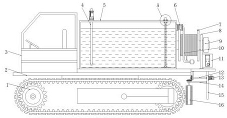
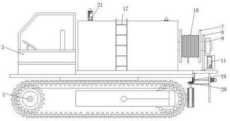
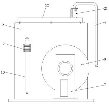
[0023] Example 1: see Figure 1-4 , a crawler traveling type large-flow drainage emergency vehicle, comprising crawler 1, a bottom plate 2 is installed on the top of the crawler 1, a cab 3 is installed on the left side of the top of the bottom plate 2, a water storage tank 5 is installed on the right side of the top of the bottom plate 2, The front end of one side of the water tank 5 is provided with a water pumping pipe 10, the top of the water pumping pipe 10 is equipped with a high-pressure water pump 6, one side of the water storage tank 5 is penetrated by a drain pipe 4, and the top of the drain pipe 4 is equipped with a drain pump 21, and the water storage tank 5 The front end is equipped with a ladder 17;

[0024] The top and bottom ends of the inner right side of the water storage tank 5 are provided with a limit seat 24, and a metal filter screen 25 is sleeved inside the limit seat 24. Connection, the bottom of the fixed plate 22 is installed with a top plate 23, the...

Embodiment 2

[0026] Embodiment 2: A mounting plate 15 is mounted on one side of the bottom of the base plate 2 , a second drive motor 13 is mounted on the top of the right side of the mounting plate 15 , a connecting shaft 12 is mounted on the top of the left side of the mounting plate 15 , and the left side of the connecting shaft 12 The first gear 19 is fixedly connected, the bottom of the left side of the mounting plate 15 is mounted with the support frame 14, the top of the support frame 14 is equipped with the second gear 20, the bottom of the first gear 19 is provided with the second gear 20, the first gear 19 and The second gears 20 form a mutually perpendicular relationship, the output end of the second drive motor 13 is connected to the connecting shaft 12, and the bottom of the second gear 20 is fixedly connected with the cleaning roller 16 through the connecting piece;

[0027] Specifically, as figure 1 , figure 2 and image 3 As shown, after the use of the connecting pipe 18...

Embodiment 3

[0028] Example 3: A support plate 8 is installed on one side of the top of the bottom plate 2, a winding roller 7 is installed between the water storage tank 5 and the support plate 8, and a connecting pipe 18 is wound on the winding roller 7, and the top of the right side of the support plate 8 is installed. A first drive motor 9 is installed, the output end of the first drive motor 9 is connected to the take-up roller 7, and a control box 11 is installed at the bottom of the right side of the support plate 8;

[0029] Specifically, as figure 1 and figure 2 As shown, when the crawler 1 is running, impurities are easily caught in the gap, and the second drive motor 13 is activated to drive the connecting shaft 12 to rotate. The connecting shaft 12 and the first gear 19 are fixedly connected, together with the first gear 19 and the second The gear 20 rotates, and the second gear 20 is used to drive the cleaning roller 16 to rotate, so as to clean the impurities in the gap of ...


PUM


Abstract

The crawler belt advancing type large-flow drainage emergency vehicle comprises a crawler belt, a bottom plate is installed on the top of the crawler belt, a cab is installed on the left side of the top of the bottom plate, a water storage tank is installed on the right side of the top of the bottom plate, a water pumping pipe penetrates through the front end of one side of the water storage tank, and a high-pressure water pump is assembled on the top of the water pumping pipe; and a top plate is mounted at the bottom of the fixed plate. By arranging a metal filter screen, a limiting seat, a top plate and a fixing plate, during use, a high-pressure water pump is started through a control box, water can be pumped into a water storage tank, after the water enters the water storage tank, impurities in the water are filtered through the metal filter screen, blockage caused by the large diameter in the water can be avoided, and the service life of the water is prolonged. After being used for a period of time, the metal filter screen is taken down by rotating a bolt at the top plate, and the metal filter screen is reset for continuous use after being cleaned, so that the problems that impurities in water are relatively large and the pipeline is easily blocked are solved.

Description

technical field [0001] The invention relates to the technical field of emergency vehicles, in particular to a crawler traveling type large-flow drainage emergency vehicle. Background technique [0002] Drainage emergency vehicles are generally used in flood drainage, urban flood control and emergency drainage. The high-pressure water pump pumps water into the water tank, and then discharges the water into the municipal pipeline to adapt to large-flow drainage work. The drainage emergency vehicle adopts a crawler traveling structure. , The grip with the ground is strong, and it can avoid the sliding of the body when it goes deep into the drainage area, which ensures the safety of use. During the process of water extraction, the impurities in the water are large, which are easy to block the pipeline and affect the efficiency of drainage; it is inconvenient for the pipeline to Rewinding and finishing takes up a lot of space; during the walking process of the crawler, impurities...

Claims


Application Information

Patent Timeline
IPC IPC(8): B62D55/06B62D55/088E03F7/10B65H75/44B65H75/42B01D29/03B01D29/96
CPCB62D55/06B62D55/0882E03F7/10E03F7/106B65H75/4486B65H75/42B65H75/425B01D29/03B01D29/96B65H2701/33
Inventor 王九意赵金叶王晓海姚宏雁
Owner REED XINXIANG ROAD INC
Why Eureka
Try Eureka