Bearing raceway surface quenching device and method

A surface quenching and bearing raceway technology, applied in quenching devices, furnaces, heat treatment equipment, etc., can solve problems affecting production efficiency, arc cracks at the starting point of joints, inconvenience, etc., to improve production efficiency, improve quenching effect, and facilitate The effect of tempering

Pending Publication Date: 2022-06-28
DALIAN OCEAN UNIV
View PDF6 Cites 0 Cited by
  • Summary
  • Abstract
  • Description
  • Claims
  • Application Information

AI Technical Summary

Problems solved by technology

[0002] Generally, during the production of bearings, it is necessary to quench the bearings to eliminate the internal stress generated during the cutting and manufacturing of the bearings. On the one hand, the physical properties are kept in a good and stable state. However, when large-scale bearings are quenched in the raceway, devices are often used to quench the surface of the raceway. The contact surface between the heated machine and the raceway is small, and the quenched part is A section of the entire ring of the raceway, and then rotate the bearing to make the quenching track form a ring, and then quench the raceway in turn, the overall efficiency is low, and, when quenching, if the user does not operate in time, it is easy to cause The phenomenon of overlapping quenching occurs at the starting point of the joint between the machine and the bearing raceway, and arc cracks and cracks are prone to occur at the starting point of the joint, and after quenching, tempering treatment is usually required, but it is difficult for general devices to treat larger The overall tempering treatment of the bearing is inconvenient and affects the production efficiency

Method used


Image

  • Bearing raceway surface quenching device and method
  • Bearing raceway surface quenching device and method
  • Bearing raceway surface quenching device and method

Examples


Embodiment Construction

[0042] The technical solutions in the embodiments of the present invention will be clearly and completely described below with reference to the embodiments of the present invention. Obviously, the described embodiments are only a part of the embodiments of the present invention, rather than all the embodiments. Based on the embodiments of the present invention, all other embodiments obtained by those of ordinary skill in the art without creative efforts shall fall within the protection scope of the present invention.

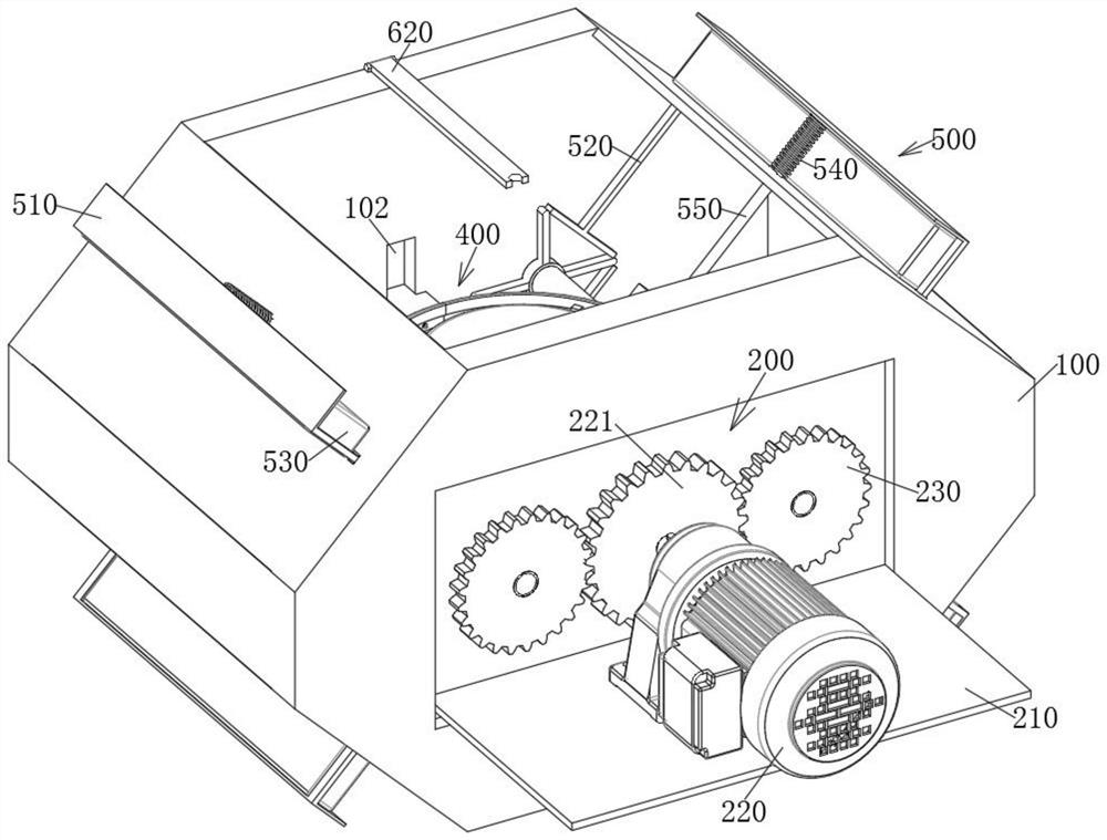
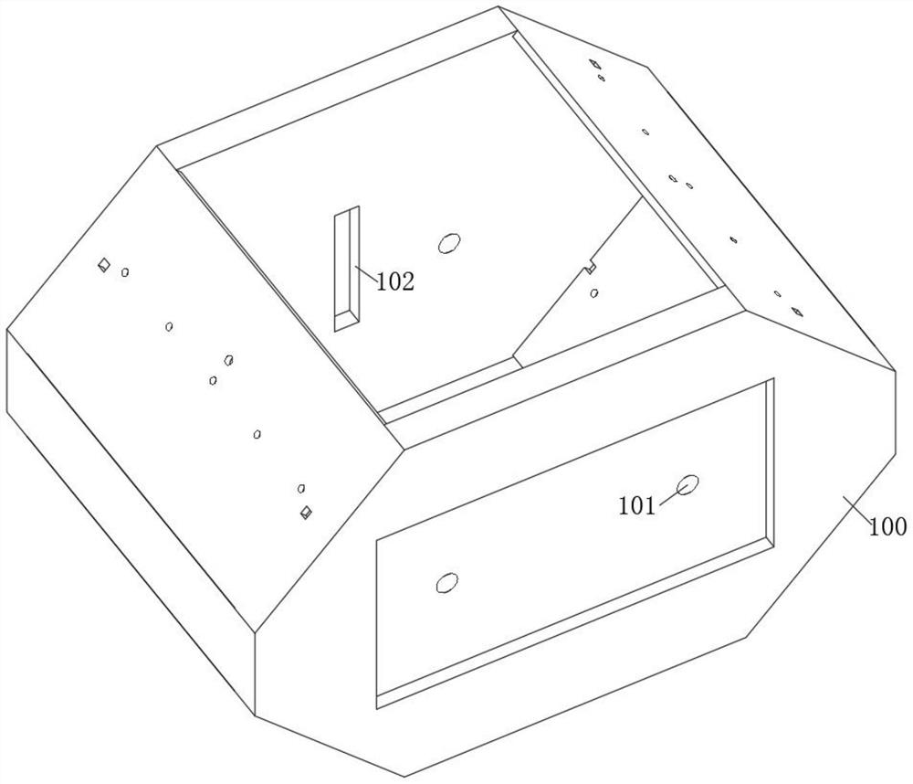
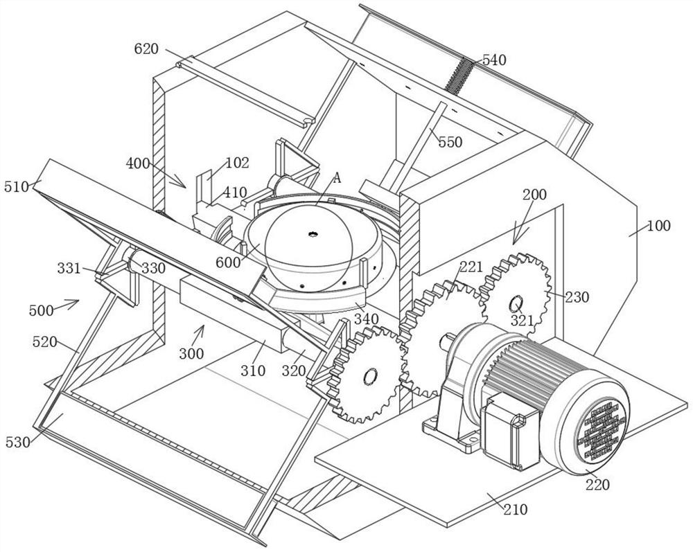
[0043] see Figure 1-12 As shown, a bearing raceway surface quenching device includes a casing 100. Two exchange mechanisms 300 for cooling and heating the bearing raceway are symmetrically arranged inside the casing 100, and the two exchange mechanisms 300 are arranged between the two exchange mechanisms 300. There is a lifting mechanism 400 for placing bearings, auxiliary mechanisms 500 are provided at the four corners of the housing 100, and a driving mechani...


PUM


Abstract

The invention relates to the technical field of bearing production, in particular to a bearing raceway surface quenching device and method.The bearing raceway surface quenching device comprises a shell, two exchange mechanisms used for cooling and heating a bearing raceway are symmetrically arranged in the shell, and a lifting mechanism used for containing a bearing is arranged between the two exchange mechanisms; and auxiliary mechanisms are arranged at four corners of the shell. According to the bearing replacing device, a bearing is placed on a tray, then a driving motor is started, the driving motor drives a main gear to rotate, the main gear drives two auxiliary gears on the two sides to synchronously rotate in the opposite direction, and the two auxiliary gears drive two replacing mechanisms to rotate in the opposite direction; the lifting mechanism and the four auxiliary mechanisms are started through abutting of the supporting arms while the two exchange mechanisms rotate, the bearing raceway is integrally heated and cooled, and overall tempering can be achieved, so that the bearing quenching effect is improved, bearing tempering is facilitated, and the bearing production efficiency is improved.

Description

technical field [0001] The invention relates to the technical field of bearing production, in particular to a bearing raceway surface quenching device and a method thereof. Background technique [0002] Generally, during the production of bearings, the bearing needs to be quenched to eliminate the internal stress generated by the bearing during cutting and manufacturing. In terms of physical properties, the physical properties are kept in a good and stable state. However, when quenching the raceway of a large bearing, a device is often used to quench the surface of the raceway. The contact surface between the heated machine and the raceway is small, and the quenched part is A section of the entire ring of the raceway, and then the bearing is rotated to make the quenched track form a ring, and the raceway is quenched in turn, the overall efficiency is low, and, during quenching, if the user does not operate in time, it will easily lead to The phenomenon of overlapping quench...

Claims


Application Information

Patent Timeline
Patent Type & Authority Applications(China)
IPC IPC(8): C21D1/667C21D9/40C21D1/18
CPCC21D1/667C21D9/40C21D9/0018C21D9/0025C21D9/0062C21D1/18
Inventor 于吉鲲张永春唐继武吴鸣宇荣治明
Owner DALIAN OCEAN UNIV
Why Eureka
Try Eureka