
End sealing well hoisting hole structure and method for recovering upper traffic of subway station in advance

A technology for subway stations and hoisting holes, which is applied to underwater structures, infrastructure engineering, passing components, etc. It can solve the problems of station roof leakage and high construction costs, achieve good sealing performance, enhance waterproof performance, and prevent pipelines from moving bit effect

Pending Publication Date: 2022-06-28
TONGZHOU CONSTR GENERAL CONTRACTING GROUP
View PDF0 Cites 0 Cited by
  • Summary
  • Abstract
  • Description
  • Claims
  • Application Information

AI Technical Summary

Problems solved by technology

[0020] Technical purpose: Aiming at the existing subway end well hoisting holes to provide channels for laying concrete in tunnels, causing delays in station acceptance and road restoration, high construction costs, and leakage of station roofs caused by reserved casings, the present invention discloses A hoisting hole structure and method for closing the head shaft of a subway station that can resume traffic opening in advance under the premise of ensuring concrete delivery, and ensure the strength and sealing of the roof, and is not easy to leak.

Method used


Image

  • End sealing well hoisting hole structure and method for recovering upper traffic of subway station in advance
  • End sealing well hoisting hole structure and method for recovering upper traffic of subway station in advance
  • End sealing well hoisting hole structure and method for recovering upper traffic of subway station in advance

Examples


Embodiment Construction

[0077] The present invention will be more clearly and completely described below by means of a preferred embodiment in conjunction with the accompanying drawings, but the present invention is not limited to the scope of the described embodiments.

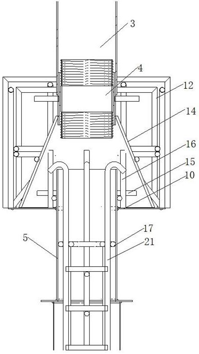
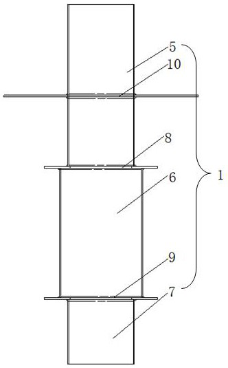
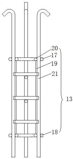
[0078] like figure 1 and figure 2 Shown is a lifting hole structure of a capping head well disclosed in the present invention for restoring the upper part of a subway station to traffic in advance, including a first embedded casing 1 for pre-embedding in the hoisting hole of the station roof and a The second embedded casing 2 of the middle plate of the station is connected to the upper end of the first embedded casing 1 with a connecting joint 4 for connecting the concrete conveying pipes 3 above and below the roof; the first embedded casing 1 includes a top-to-bottom The first pipe section 5, the second pipe section 6 and the third pipe section 7 are arranged concentrically. The diameter of the second pipe section 6 is larger tha...


PUM


Abstract

The invention discloses a sealing end well hoisting hole structure and method for recovering traffic on the upper portion of a subway station in advance, and the sealing end well hoisting hole structure comprises a first pre-buried sleeve used for being pre-buried in a station top plate hoisting hole and a second pre-buried sleeve used for being pre-buried in a station middle plate. The upper end of the first embedded sleeve is connected with a connecting joint for communicating the concrete conveying pipes above and below the top plate; a concrete reinforcing structure and a waterproof assembly are arranged on the first embedded sleeve, and a reinforcing reinforcement cage is arranged on the outer surface of the waterproof assembly; the first embedded sleeve and the second embedded sleeve are each provided with a blocking reinforcement cage for supporting and blocking the interior of the pipeline after concrete conveying is completed. An inlet of the concrete conveying pipe is formed in the side road of the road, a sealing cover is arranged on a pipe opening, a well hole is reserved in the pipe opening of the concrete conveying pipe, and a cover plate is additionally arranged on the well hole, so that in-advance traffic is facilitated, and the construction progress is accelerated; and the waterproof assembly, the plugging reinforcement cage and other structures are utilized, the overall structural strength is enhanced, and cracking and leakage of concrete are avoided.

Description

technical field [0001] The invention relates to the technical field of subway construction, and in particular relates to a structure and a method for restoring the hoisting hole structure and method of an end-capped head well for resuming the upper part of a subway station open to traffic in advance. Background technique [0002] Underground subway stations are generally 2 to 3-storey structures, including the main structure of the station, the entrances and exits of auxiliary structures, and the wind pavilion. Hoisting holes are reserved on the top and middle plates at both ends of the station. The size of the hole is generally 12m×8m. The underground tunnel is constructed by shield machine. The shield machine needs to be hoisted into the station for assembly. The major components are lifted out of the station, and materials and equipment are loaded and transported into the station. The number of reserved holes in the station end well is the same as the number of tunnels. ...

Claims


Application Information

Patent Timeline
Patent Type & Authority Applications(China)
IPC IPC(8): E02D29/045E02D29/12E02D29/14E02D15/02E01B29/00F16L5/02F16L15/04
CPCE02D29/04E02D29/045E02D29/12E02D29/14E02D15/02E01B29/005F16L5/02F16L15/04E02D2300/002E02D2300/0029
Inventor 邢春华袁晓虎李洲华季斌邱欣邢炜亮
Owner TONGZHOU CONSTR GENERAL CONTRACTING GROUP
Learn More