Tunnel top cavity supporting method

A technology for tunnels and cavities, which is applied in the direction of tunnels, earthwork drilling, tunnel lining, etc., which can solve problems such as large safety risks, adverse effects on construction progress, and long waiting times, so as to save grout consolidation time and ensure safety. Quick cost, improve the effect of treatment effect

Active Publication Date: 2022-06-28
CHINA HYDROELECTRIC ENGINEERING CONSULTING GROUP CHENGDU RESEARCH HYDROELECTRIC INVESTIGATION DESIGN AND INSTITUTE
View PDF19 Cites 2 Cited by
  • Summary
  • Abstract
  • Description
  • Claims
  • Application Information

AI Technical Summary

Problems solved by technology

[0004] The disadvantages of the first treatment method above are: first, it may take a long time to wait, and failure to support in time may increase the risk of landslides; second, without taking any protective measures, the cavity at the top of the tunnel is supported. However, there is still a relatively large safety risk; thirdly, backfilling the cavity with grouting is a complex process with strict requirements on the process, and it will take a certain time for the grout to consolidate, which will adversely affect the construction progress
The above-mentioned second treatment method has the following disadvantages: On the one hand, it takes a certain amount of time to cover the face of the tunnel by backfilling the slag material, and the slag body needs to be transported out of the slag later, which has a great impact on the construction progress ; On the other hand, the adverse effect of backfilling the cavity with grouting is the same as the third point of the first treatment method.

Method used


Image

  • Tunnel top cavity supporting method

Examples


Embodiment Construction

[0028] The present invention will be further described below in conjunction with accompanying drawing.

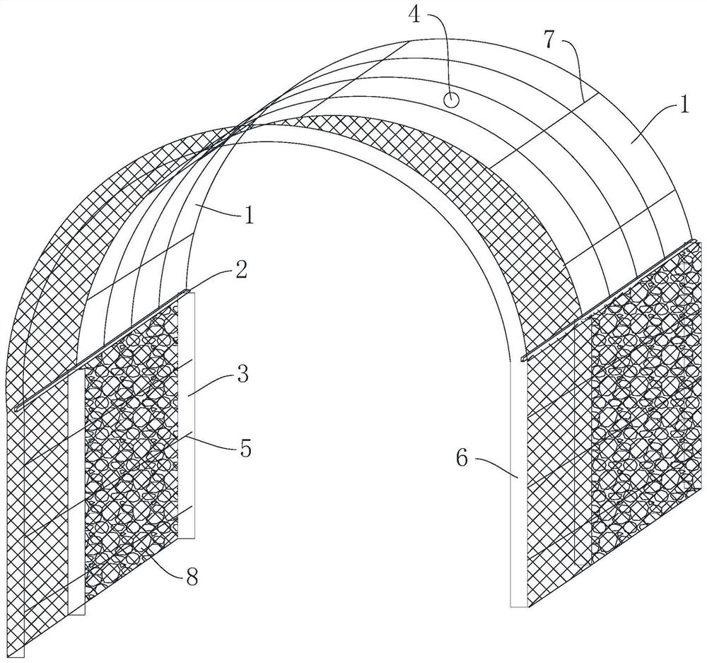
[0029] like figure 1 As shown, the tunnel top cavity support method of the present invention is used for the working condition where an unstable cavity appears at the top of the tunnel near the tunnel face during the blasting and excavation of the weak and broken surrounding rock tunnel section. The support treatment method includes the following step:

[0030] S1. Make the steel arch 1, the arch support 2, the arch foot 3 and the arch foot fixing parts for spare use. The steel arch 1 is a strip-shaped steel plate bent into an arch shape. The steel arch 1 can also be made of other metals or alloys. The steel arch 1 is used to install on the top of the tunnel and form a support for the tunnel roof. The arch should preferably be in line with the tunnel excavation contour. For example, the steel arch 1 is made of ordinary steel plate with a thickness of 1-2 cm, and the widt...


PUM


Abstract

The invention discloses a method and a structure for supporting a cavity at the top of a tunnel, relates to the field of geotechnical engineering, and aims to support an unstable cavity at the top of the tunnel after the tunnel is broken so as to safely and quickly pass through a soft and broken surrounding cavern section. According to the technical scheme, the tunnel top cavity supporting method comprises the steps that in the blasting excavation period of a soft broken surrounding rock cave section, an unstable cavity appears at the position, close to the tunnel face, of the top of a tunnel, and steel arch pieces, arch piece supports, arch feet and arch foot fixing pieces are manufactured for standby application; then bottom foot scum of the tunnel is removed, arch feet are erected on the two side walls of the tunnel respectively, and arch piece supports and steel arch pieces are fixedly installed on the arch feet respectively; slag is discharged, and the steel arch pieces of the remaining tunnel sections are installed till the tunnel face is reached; steel bars are hung on the inner sides of the arch feet, concrete is sprayed, and a structural layer is formed; and finally, the unstable cavity is backfilled through the backfilling holes. The method is used for treating the unstable cavity appearing at the top of the tunnel, close to the tunnel face, of the soft and broken surrounding cavern section.

Description

technical field [0001] The invention relates to the field of geotechnical engineering, in particular to a method and structure for supporting and treating the top cavity that occurs during tunnel excavation. Background technique [0002] During the excavation of the tunnel, the weak and broken surrounding rock section, especially the carbonaceous slate geological conditions with well-developed groundwater, faces a greater risk of landslides. If the situation is not dealt with in time, it may cause greater losses. [0003] At present, the treatment measures for this working condition include the following methods: first, after the loose rock mass at the top of the tunnel is basically stable and no larger rock-soil blocks fall, carry out slag removal construction, and then carry out the slag removal construction, and then carry out the slag removal construction on the cavity part. Carry out support and backfill grouting. Second, if the loose rock and soil mass at the top of ...

Claims


Application Information

Patent Timeline
Patent Type & Authority Applications(China)
IPC IPC(8): E21D11/18E21D11/10E21D11/28
CPCE21D11/183E21D11/105E21D11/107E21D11/28Y02E10/20
Inventor 李正
Owner CHINA HYDROELECTRIC ENGINEERING CONSULTING GROUP CHENGDU RESEARCH HYDROELECTRIC INVESTIGATION DESIGN AND INSTITUTE
Why Eureka
Try Eureka