
Heat dissipation device and fishing lamp

A technology of heat dissipation device and heat dissipation parts, which is applied in the field of fishing tools, can solve the problems of only being in contact with local areas of heat dissipation plates and fins, affecting the heat dissipation of fish-collecting lamps, and overheating, so as to avoid small heat dissipation areas and save energy. The amount of usage and the effect of improving heat dissipation efficiency

Active Publication Date: 2022-06-28
徐连城
View PDF17 Cites 0 Cited by
  • Summary
  • Abstract
  • Description
  • Claims
  • Application Information

AI Technical Summary

Problems solved by technology

[0004] However, in the existing heat dissipation devices, the heat conduction fins are often made of a whole heat dissipation plate or fins, and when connected to the lamp tube, the lamp tube is only connected to the local area of ​​the heat dissipation plate and the fins
Therefore, when the lamp tube generates heat and transmits heat through the heat conducting fins, the heat can only contact a local area of ​​the heat sink and the fins, resulting in overheating of the local area of ​​the fins, while the rest of the parts are too cold, which affects the heat dissipation of the fish-collecting lamp.

Method used


Image

  • Heat dissipation device and fishing lamp
  • Heat dissipation device and fishing lamp
  • Heat dissipation device and fishing lamp

Examples


Embodiment Construction

[0044] The embodiments of the present application will be described below with reference to the accompanying drawings in the embodiments of the present application. Obviously, the described embodiments are only a part of the embodiments of the present application, but not all of the embodiments.

[0045] It should be noted that when a component is considered to be "connected" to another component, it can be directly connected to another component or there may be an intervening component at the same time. When a component is considered to be "set on" another component, it may be located directly on the other component or may co-exist with an intervening component. The terms "top," "bottom," "top," "bottom," "left," "right," "front," "back," and similar expressions are used herein for illustrative purposes only.

[0046] Embodiments of the present application provide a heat dissipation device, comprising:

[0047] a first heat sink, a through hole is formed along its axis, and ...


PUM


Abstract

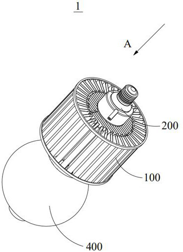
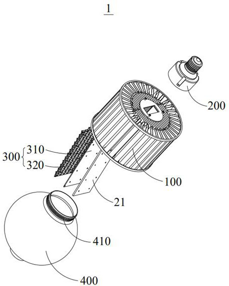
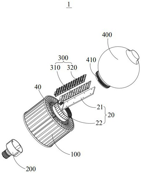
The invention provides a heat dissipation device which comprises a first heat dissipation piece, a second heat dissipation piece, a first heat dissipation piece, a second heat dissipation piece and a third heat dissipation piece, the first heat dissipation piece is provided with a through hole along the axis, and the first heat dissipation piece is provided with a first heat conduction surface; the heat conduction piece comprises a contact part and a heat conduction part arranged on the contact part, the peripheral surface of the heat conduction part is attached to the first heat conduction surface in a surrounding manner, and the heat conduction part is encircled to form an accommodating space; the second heat dissipation piece is arranged in the containing space, and the outer circumferential face of the second heat dissipation piece is attached to the inner circumferential face of the heat conduction part. The peripheral surface of the heat conduction part is attached to the first heat conduction surface in a surrounding mode, and the peripheral surface of the second heat dissipation part is attached to the inner peripheral surface of the heat conduction part, so that when heat is transmitted to the heat conduction part through the contact part, the heat on the heat conduction part can be dissipated through the first heat dissipation part and the second heat dissipation part at the same time; therefore, the problem that heat is accumulated and is difficult to dissipate when the heat is only dissipated through one of the first heat dissipation piece and the second heat dissipation piece is solved, and the heat dissipation efficiency is improved.

Description

technical field [0001] The present application relates to the technical field of fishing tools, and in particular, to a heat sink and a fishing light. Background technique [0002] The fish-collecting light system is an essential tool for trapping phototactic fish. Its working principle is to use the phototaxis of fish to light up lights in the dark to attract fish to gather, so as to facilitate centralized fishing or fishing. [0003] At present, most of the heat sinks in the fish-collecting lamps on the market are made of traditional aluminum extrusion molding or high-pressure die-casting aluminum die-casting. The heat generated by the lamp is exported to the fins for heat dissipation. [0004] However, in the existing heat dissipation device, the heat-conducting fin is usually made of a whole heat-dissipating plate or fin, and when connecting with the lamp tube, the lamp tube is only connected with the partial area of ​​the heat-dissipating plate and the fin. Therefore,...

Claims


Application Information

Patent Timeline
Patent Type & Authority Applications(China)
IPC IPC(8): F21V29/70F21S8/00F21V29/77F21V29/83
CPCF21V29/70F21S8/00F21V29/77F21V29/83
Inventor 梅志洪徐连城
Owner 徐连城
Learn More