Supercharge Your Innovation With Domain-Expert AI Agents!

Magnetic pole module fixing device, rotor comprising same and permanent magnet wind driven generator

A technology for wind power generators and fixing devices, applied in the direction of electromechanical devices, magnetic circuits, electrical components, etc., can solve the problems of high cost, T-shaped groove processing requirements and high precision, and high difficulty in T-shaped groove processing, so as to reduce the difficulty of processing and cost effects

Pending Publication Date: 2022-06-28
SHANGHAI ELECTRIC WIND POWER GRP CO LTD +1
View PDF6 Cites 0 Cited by
  • Summary
  • Abstract
  • Description
  • Claims
  • Application Information

AI Technical Summary

Problems solved by technology

[0004] In the above method, the T-shaped slot needs to be processed on the inner surface of the rotor house. Due to the large diameter of the rotor house, it needs to be processed by a large-scale high-precision CNC gantry turning and milling compound machine tool, and the processing of the T-shaped slot is relatively difficult. And high precision, occupying a long time machine tool, high cost

Method used


Image

  • Magnetic pole module fixing device, rotor comprising same and permanent magnet wind driven generator
  • Magnetic pole module fixing device, rotor comprising same and permanent magnet wind driven generator
  • Magnetic pole module fixing device, rotor comprising same and permanent magnet wind driven generator

Examples


Embodiment Construction

[0049] The present invention is further described below by means of examples, but the present invention is not limited to the scope of the described examples.

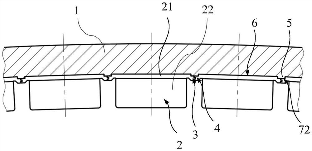
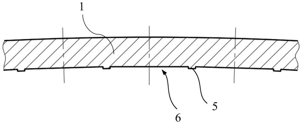
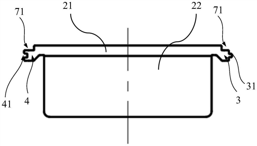
[0050] This embodiment provides a permanent magnet wind generator, including a rotor, such as figure 1 As shown, the rotor includes a rotor housing 1, a magnetic pole module 2 and a magnetic pole module fixing device, and the magnetic pole module fixing device is connected with the magnetic pole module 2 for fixing the magnetic pole module 2 to the rotor housing 1 to ensure the magnetic pole module. The group 2 will not easily fall off the rotor house 1 during the operation of the permanent magnet wind turbine, which improves the stability of the use process.

[0051] like Figure 1-Figure 3 As shown, the magnetic pole module fixing device includes a convex part 3 and a first concave part 4, and the convex part 3 and the first concave part 4 are respectively arranged in the direction of the adjacent two magnetic pole ...


PUM


Abstract

The invention discloses a magnetic pole module fixing device, a rotor comprising the same and a permanent magnet wind driven generator, the magnetic pole module fixing device comprises a convex part and a first concave part, and the convex part and the first concave part are respectively arranged on the side surfaces, facing each other, of two adjacent magnetic pole modules along the circumferential direction of the rotor; the protruding part comprises a boss protruding outwards from the circumferential side face of the magnetic pole module, and the first sunken part comprises a groove sunken inwards from the circumferential side face, away from the corresponding magnetic pole module, of the first sunken part. For two adjacent magnetic pole modules in the circumferential direction of the rotor, the boss of one magnetic pole module is clamped with the groove of the other magnetic pole module. Movement of the magnetic pole modules in the radial direction of the rotor is limited through mutual restraining of the two adjacent magnetic pole modules in the circumferential direction of the rotor, no special requirement for the shape of the magnetic pole module fixing groove exists, the magnetic pole module fixing groove can be in the shape easy to machine, and therefore the machining difficulty and cost of the magnetic pole module fixing groove are reduced.

Description

technical field [0001] The invention relates to the field of wind power generation, in particular to a magnetic pole module fixing device, a rotor including the same, and a permanent magnet wind generator. Background technique [0002] The operating environment of wind turbines is often a high-humidity and high-salt environment, especially offshore wind turbines, where the operating conditions are relatively harsh. ) and the base plate made of metal magnetic conductive material (low carbon steel plate) to form a magnetic pole module. [0003] The rotor magnets of the outer rotor permanent magnet direct drive wind turbine are mostly fixed on the yoke surface of the inner wall of the rotor by surface-mounting. A method, specifically machining a plurality of T-slots on the inner wall of the rotor, and implementing the magnetic pole module into a shape that matches the T-slots, the T-slots extend from the brake disc side of the rotor to the hub side, and terminate at At a dist...

Claims


Application Information

Patent Timeline
IPC IPC(8): H02K1/2791
CPCH02K1/2786
Inventor 孙永岗卢江跃吴立建施杨
Owner SHANGHAI ELECTRIC WIND POWER GRP CO LTD
Features
  • R&D
  • Intellectual Property
  • Life Sciences
  • Materials
  • Tech Scout
  • Unparalleled Data Quality
  • Higher Quality Content
  • 60% Fewer Hallucinations
Learn More