Copper foil carrier and manufacturing method thereof
A technology of copper foil carrier and production method, which is applied in the direction of printed circuit manufacturing, conductive pattern formation, printed circuit, etc., can solve the problems of high temperature-resistant release film cost, abnormal pressing quality, copper foil dust particle pollution, etc., to achieve good Adhesion and peel strength, reduction of abnormal pressing quality, and reduction of fine particle impurities
- Summary
- Abstract
- Description
- Claims
- Application Information
AI Technical Summary
Problems solved by technology
Method used
Image
Examples
Embodiment 1
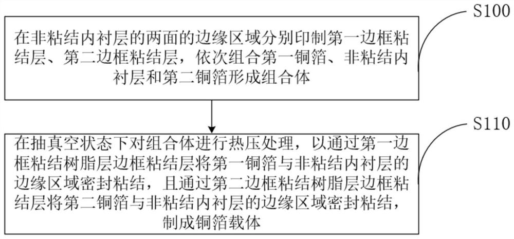
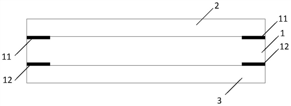
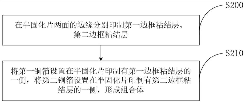
[0052] Optionally, the non-bonded inner liner 1 includes a prepreg, please refer to image 3 , in a method for manufacturing a copper foil carrier provided by the present invention, the “first frame bonding layer 11 and the second frame bonding layer 12 are respectively printed on the edges of both sides of the non-bonded inner lining layer 1, and then combined in sequence. The first copper foil 2, the non-adhesive lining layer 1 and the second copper foil 3 form a composite body" specifically including:
[0053] S200: The first frame adhesive layer 11 and the second frame adhesive layer 12 are respectively printed on the edges of both sides of the prepreg, and the process proceeds to step S210.
[0054] S210: Disposing the first copper foil 2 on the side of the prepreg on which the first frame adhesive layer 11 is printed, and disposing the second copper foil 3 on a side of the prepreg on which the second frame adhesive layer 12 is printed side to form a composite.
Embodiment 2
[0056] Optionally, the non-bonded inner lining layer 1 includes at least two prepregs laminated and combined, please refer to Figure 4 , in a method for manufacturing a copper foil carrier provided by the present invention, the “first frame bonding layer 11 and the second frame bonding layer 12 are respectively printed on the edges of both sides of the non-bonded inner lining layer 1, and then combined in sequence. The first copper foil 2, the non-adhesive lining layer 1 and the second copper foil 3 form a composite body" specifically including:
[0057] S300 : respectively print a first frame adhesive layer 11 and a second frame adhesive layer 12 on the edges of the two outermost prepregs on both sides of the non-bonded inner lining layer 1 , and proceed to step S310 .
[0058] S310: Arrange the first copper foil 2 on the side of the non-adhesive lining layer 1 on which the first frame adhesive layer 11 is printed, and arrange the second copper foil 3 on the non-adhesive lin...
Embodiment 3
[0060] This embodiment is based on Embodiment 2, and adds the solution that at least one of the opposite surfaces of the two adjacent prepregs in the non-bonded inner lining layer is provided with a bonding resin layer. , the multi-layer prepreg structure can be pressed and combined to form the non-bonded inner lining layer 1 structure more closely.
[0061] The application of the method provided by the present invention will be described below by taking the solution of manufacturing the copper foil carrier using different materials and methods as an example.
PUM
| Property | Measurement | Unit |
|---|---|---|
| thickness | aaaaa | aaaaa |
| thickness | aaaaa | aaaaa |
| thickness | aaaaa | aaaaa |
Abstract
Description
Claims
Application Information
 - R&D
- Intellectual Property
- Life Sciences
- Materials
- Tech Scout
- Unparalleled Data Quality
- Higher Quality Content
- 60% Fewer Hallucinations
Browse by: Latest US Patents, China's latest patents, Technical Efficacy Thesaurus, Application Domain, Technology Topic, Popular Technical Reports.
© 2025 PatSnap. All rights reserved.Legal|Privacy policy|Modern Slavery Act Transparency Statement|Sitemap|About US| Contact US: help@patsnap.com


