Circulating filtration puncture outfit with lens assembly
A lens assembly and circulation filtering technology, which is applied in the direction of puncture needles, laparoscopes, endoscopes, etc., can solve the problems of harming the physical and mental health of medical staff, damage, and affecting the sight of medical staff, so as to avoid accidental injury, accurate surgical operation, and maintain Observe the effect of field of view
- Summary
- Abstract
- Description
- Claims
- Application Information
AI Technical Summary
Problems solved by technology
Method used
Image
Examples
Embodiment 1
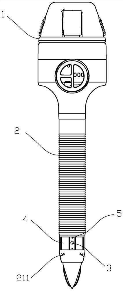
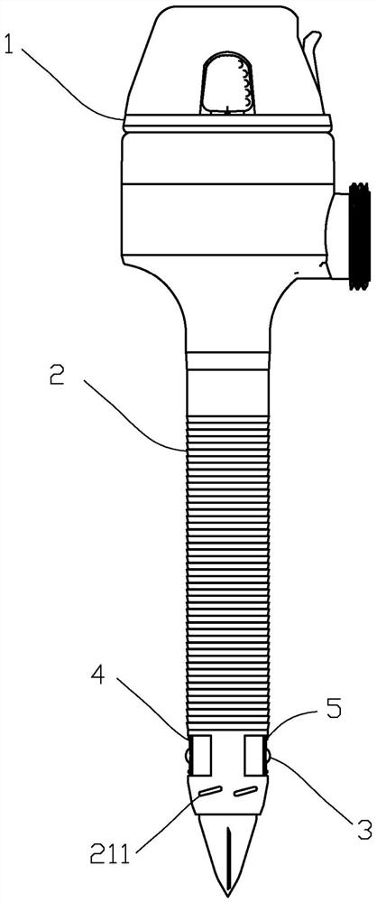
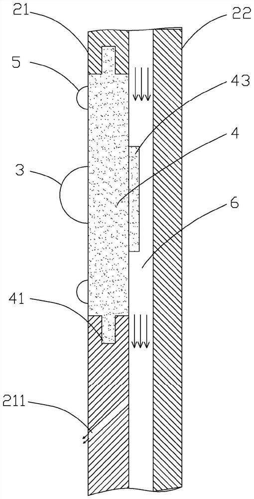
[0032] see Figure 1-Figure 5 The basic structure of a circulating filter puncture device with a lens assembly provided in this embodiment can refer to the puncture device of CN109498122B, that is, it also includes a puncture rod 1 and a sheath tube assembly 2 sleeved on the outside of the puncture rod. The sheath tube assembly includes an outer tube 21 and an inner tube 22 . The outer tube is sleeved on the outside of the inner tube to form an interlayer. The interlayer is distributed with an air intake channel 6 and a smoke exhaust channel 7 isolated from each other by a partition 8 . The air inlet channel 6 communicates the air inlet with the air outlet 211 , the air inlet is arranged at the head of the outer tube 21 , and the air outlet 211 is arranged at the thin end of the outer tube 21 . The smoke exhaust passage 7 communicates the smoke outlet with the smoke outlet, the smoke outlet is arranged at the thin end of the inner pipe 22 , and the smoke outlet is arranged at ...
Embodiment 2
[0047] The circulating filter piercer with lens assembly provided in this embodiment is further improved on the basis of the piercer in Embodiment 1. The improvements are as follows: please refer to Figure 6-Figure 7 , a plurality of air injection holes 44 are formed on the lens carrier plate 4 , preferably, these air injection holes 44 are distributed around the lens 3 , the air injection holes are communicated with the air inlet channel 6 , and the air jet direction of each air injection hole is directed to the surface of the lens 3 . Wherein, by setting the aperture of the air jet hole 44 to be smaller, for example, about 1 mm or even smaller, a larger jet air flow velocity can be obtained (the air flow direction is such as Image 6 The slanted arrow in the ), so that the surface of the lens 3 can be kept purging, and a clear view can always be obtained without the need for additional cleaning mechanisms. Preferably, a self-cleaning coating or the like may also be provided...
PUM
 Abstract
Description
Claims
Application Information
 - R&D
- Intellectual Property
- Life Sciences
- Materials
- Tech Scout
- Unparalleled Data Quality
- Higher Quality Content
- 60% Fewer Hallucinations
Browse by: Latest US Patents, China's latest patents, Technical Efficacy Thesaurus, Application Domain, Technology Topic, Popular Technical Reports.
© 2025 PatSnap. All rights reserved.Legal|Privacy policy|Modern Slavery Act Transparency Statement|Sitemap|About US| Contact US: help@patsnap.com


