Battery replacement station assembling method
An assembly method and a technology for replacing power stations, which are applied to charging stations, electric vehicles, transportation and packaging, etc., can solve the problems of reduced construction costs, disadvantages, and poor scalability of power stations, and achieve reduced construction costs, good scalability, and vertical Effective use of space
- Summary
- Abstract
- Description
- Claims
- Application Information
AI Technical Summary
Problems solved by technology
Method used
Image

Examples
Embodiment 1
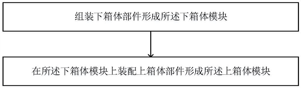
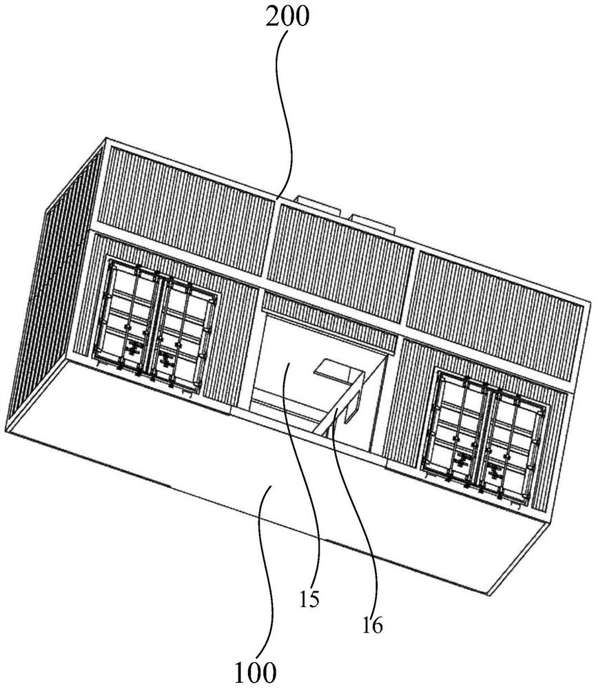
[0116] like figure 1 and figure 2 As shown, the assembling method of the power exchange station according to the embodiment of the present invention is used to assemble the power exchange station, and the power exchange station includes the upper case module 200 and the lower case module 100 which are detachably connected. The assembly method of the power exchange station includes: assembling the lower case parts to form a Lower case module 100 ; the upper case module 200 is formed by assembling upper case parts on the lower case module 100 .
[0117] On the production line, the lower box body components are first assembled to form the lower box body module 100, and then the upper box body components are assembled on the lower box body module 100 to form the upper box body module 200, so that the lower box body modules 100 are assembled on the production line respectively. And the upper case module 200, the lower case module 100 and the upper case module 200 realize modulari...
Embodiment 2
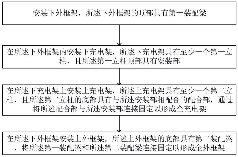
[0121] like image 3 , Figure 4 and Figure 5As shown, in this embodiment, assembling the lower box body components to form the lower box body module 100 includes: installing the lower outer frame 11 , the top of which has a first assembly beam 111 ; installing the lower outer frame 11 for charging The rack 12, the lower charging rack 12 has at least one first column 121, and the top of the first column 121 has a mounting portion 122. When assembling the lower box module 100 on the production line, the first assembly beam 111 is arranged on the top of the lower outer frame 11 to effectively strengthen the overall structural strength of the lower box module 100. The first column 121 of the lower charging rack 12 can The structural strength of the lower charging stand 12 is strengthened, and has a strong supporting effect. At the same time, the subsequent assembly with the upper box body is facilitated by the first assembly beam 111 and the mounting portion 122 of the first ...
Embodiment 3
[0127] like Image 6 and Figure 7 As shown, connecting and fixing the first assembling beam 111 and the second assembling beam 211 to form a full outer frame includes: arranging first positioning parts 112 at the four top corners of the lower outer frame 11; A second positioning portion 212 is provided at the corner; the first positioning portion 112 and the second positioning portion 212 are aligned and fixed. The first positioning portion 112 and the second positioning portion 212 have precise positioning functions. When assembling the full outer frame on the production line, the first positioning portion 112 and the second positioning portion 212 are aligned and fixed, so that the first assembly beam 111 The connection and fixation with the second assembly beam 211 is more convenient, and the installation accuracy is higher, which greatly improves the safety and stability of the power exchange station. At the same time, the assembly efficiency is high.
PUM
 Abstract
Description
Claims
Application Information
 - R&D
- Intellectual Property
- Life Sciences
- Materials
- Tech Scout
- Unparalleled Data Quality
- Higher Quality Content
- 60% Fewer Hallucinations
Browse by: Latest US Patents, China's latest patents, Technical Efficacy Thesaurus, Application Domain, Technology Topic, Popular Technical Reports.
© 2025 PatSnap. All rights reserved.Legal|Privacy policy|Modern Slavery Act Transparency Statement|Sitemap|About US| Contact US: help@patsnap.com