Water-stacked landscape discharge chute

A chute and landscape technology, applied in the field of chute structure, can solve the problems of poor ecological landscape effect of exposed concrete and low flood discharge frequency of chute, and achieve the effects of convenient construction, low plate height and high impact strength

Pending Publication Date: 2022-07-01
浙江省水利水电勘测设计院有限责任公司
View PDF0 Cites 0 Cited by
  • Summary
  • Abstract
  • Description
  • Claims
  • Application Information

AI Technical Summary

Problems solved by technology

[0005] The purpose of the present invention is to overcome the shortcomings of the existing spillway chute, such as the low frequency of flood discharge and the poor ecological landscape effect of exposed concrete, and proposes a discharge that meets the requirements of ecological flow discharge, has the effect of cascading waterfall landscape, can discharge all year round, and is easy to construct. groove structure

Method used


Image

  • Water-stacked landscape discharge chute
  • Water-stacked landscape discharge chute
  • Water-stacked landscape discharge chute

Examples


Embodiment Construction

[0027] The present invention will be described in further detail below with reference to the accompanying drawings.

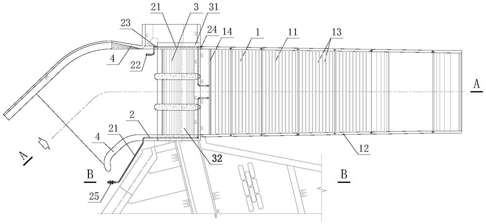
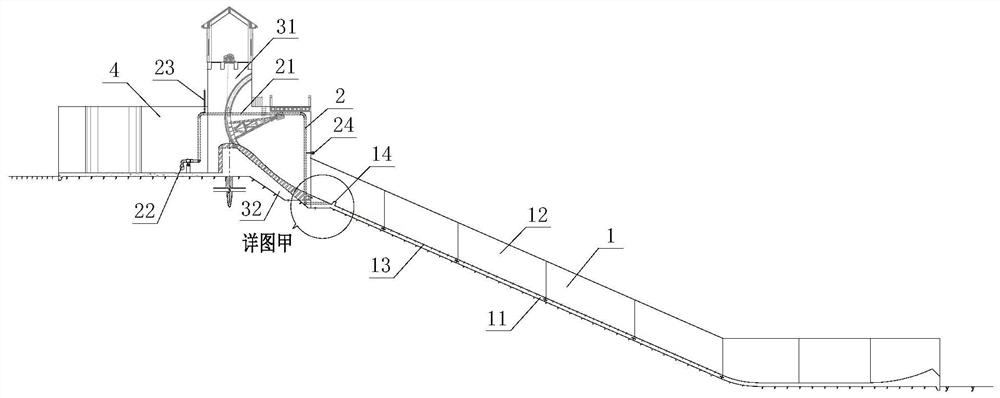
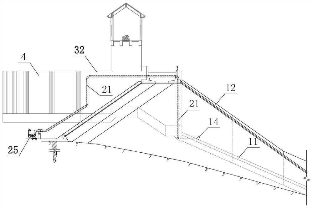
[0028] like Figure 1 to Figure 5 As shown in the figure, the present invention is a landscape gutter with stacked water, including a stacked water gutter 1 and a water delivery system 2 .

[0029] The stacked water chute 1 is located downstream of the spillway sluice 3 and can be modified on the basis of the conventional chute, including the bottom plate 11 , the side wall 12 , the drop sill 13 and the catchment sill 14 . The bottom plate 11 and the side wall 12 are the reinforced concrete structures of the conventional chute, located at the bottom and both sides of the stacked water chute respectively; the drop sill 13 is located on the upper part of the bottom plate 11, and the surface full section of the bottom plate 11 of the stacked water chute 1 at a certain interval The cascade arrangement is the main structure for forming the stacked water waterfall; ...


PUM


Abstract

The invention discloses a stacked water landscape discharge chute which comprises a stacked water discharge chute body and a water conveying system. The water stacking discharge chute comprises a bottom plate, a side wall, a drop sill and a water collecting sill; the side walls are located at the bottom and on the two sides of the stacked water discharge chute, and the drop sill is located on the upper portion of the bottom plate. The drop sill comprises an L-shaped plate, an anchor bolt and a rubber gasket, the L-shaped plate is fixed to the surface of the bottom plate through the anchor bolt, the rubber gasket is clamped between the L-shaped plate and the bottom plate, and water leakage is reduced. The water collecting ridge is located at the head end of the water stacking discharge chute and stores water stably on the initial water surface. The water delivery system comprises a water delivery pipe, a water intake, a vacuum pipe, a control valve and a submersible pump, and the water intake, the vacuum pipe, the control valve and the water delivery pipe form a siphon for self-flowing water diversion when the normal water level of the reservoir is higher than the water collecting ridge; the submersible pump is located at the front end of the water conveying pipe and used for pumping water to the sump when the reservoir normal water level is lower than the sump. The method has the advantages that the surface landscape of the discharge chute is improved, the landscape effect under the dam is improved, channels for discharging ecological flow are enriched, flood discharge is basically not affected, and construction is convenient.

Description

technical field [0001] The invention relates to a chute structure in a water conservancy and hydropower project, in particular to a chute structure with the effect of overlapping water landscape by upgrading and transforming a chute on a steep slope of a conventional spillway. Background technique [0002] The spillway chute is the main building in the reservoir hub, and it is the channel for the flood discharge of the reservoir. It is generally in an anhydrous drought state during most of the non-flood seasons or dry seasons. [0003] At present, more and more reservoir projects are being developed in combination with ecological landscape tourism. Conventional chutes are in a state of cut-off for a long time due to the low frequency of flood discharge through spillways. When the vegetation on both sides of the bank slope spillway is well covered, the large-area exposed concrete structure on the bottom of the chute has a greater impact on the landscape. As the requirements f...

Claims


Application Information

Patent Timeline
Patent Type & Authority Applications(China)
IPC IPC(8): E02B8/06
CPCE02B8/06
Inventor 赖勇周琮辉刘大康宋汉耀常贵宾
Owner 浙江省水利水电勘测设计院有限责任公司
Why Eureka
Try Eureka