
Heat dissipation plate of parallel multi-fluid-channel flow equalizing structure and optical fiber laser

A technology of fiber lasers and fluid channels, applied in lasers, laser parts, phonon exciters, etc., can solve the problems of medium leakage, failure to meet demand, occupying space of fiber lasers, etc., and achieve uniform temperature distribution, stable and reliable work Effect

Pending Publication Date: 2022-07-01
天津凯普林光电科技有限公司
View PDF0 Cites 0 Cited by
  • Summary
  • Abstract
  • Description
  • Claims
  • Application Information

AI Technical Summary

Problems solved by technology

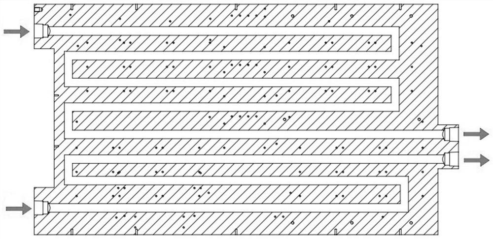
[0004] In the process of realizing the present invention, the inventor has considered several simple and intuitive designs that meet the requirements of current sharing, but they at least have the following problems: refer to figure 1 , in the considered design of a fiber laser cooling device, the inlet and outlet of the cooling medium are located on both sides of the cooling plate, and the number of inlets and outlets of the cooling medium is multiple. Adding confluence and diversion joints outside the board requires a large space inside the fiber laser, and additional man-hours for pipe connection are required, and there is a risk of medium leakage
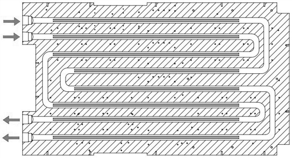
refer to figure 2 , in another fiber laser cooling device design that has been considered, although the cooling medium inlet and outlet are located on the same side of the heat sink, the number of cooling medium inlets and outlets is also multiple, and in some applications In some occasions, the number of inlet and outlet of the cooling medium needs to be limited to one, so this design cannot meet the demand

Method used


Image

  • Heat dissipation plate of parallel multi-fluid-channel flow equalizing structure and optical fiber laser
  • Heat dissipation plate of parallel multi-fluid-channel flow equalizing structure and optical fiber laser
  • Heat dissipation plate of parallel multi-fluid-channel flow equalizing structure and optical fiber laser

Examples


Embodiment Construction

[0030] The following describes in detail the embodiments of the present invention, examples of which are illustrated in the accompanying drawings, wherein the same or similar reference numerals refer to the same or similar elements or elements having the same or similar functions throughout. The embodiments described below with reference to the accompanying drawings are exemplary, only used to explain the present invention, and should not be construed as a limitation of the present invention. On the contrary, embodiments of the present invention include all changes, modifications and equivalents falling within the spirit and scope of the appended claims.

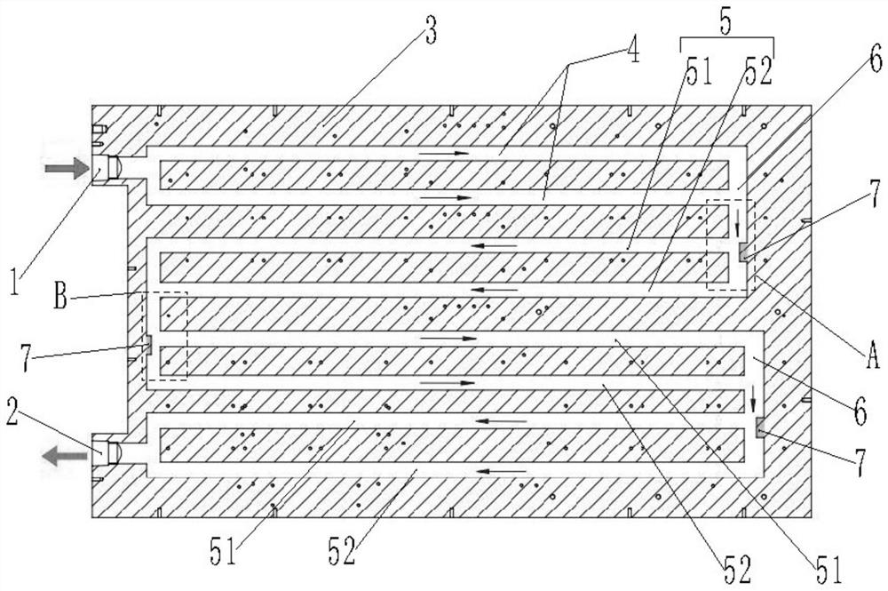
[0031] image 3 It is a schematic diagram of a heat dissipation plate with a parallel multi-fluid channel flow-equalizing structure provided by an embodiment of the present invention.

[0032] see image 3 , This embodiment provides a heat dissipation plate with a parallel multi-fluid channel flow-equalizing structure. The...


PUM


Abstract

The invention provides a heat dissipation plate of a parallel multi-fluid-channel flow equalizing structure. The heat dissipation plate comprises an inlet and an outlet. The first parallel fluid channel is arranged on the heat dissipation plate, and the inlet end of the first parallel fluid channel is connected with the inlet; the flow equalizing fluid channel is arranged on the heat dissipation plate, the flow equalizing fluid channel comprises a collecting pipe, a second parallel fluid channel and a check block, the collecting pipe is connected with the outlet end of the first parallel fluid channel and the inlet end of the second parallel fluid channel, the check block is installed in the collecting pipe, and the check block is connected with the outlet end of the first parallel fluid channel and the inlet end of the second parallel fluid channel. The flow equalizing fluid channel is used for enabling the flow of the cooling medium in each fluid channel in the second parallel fluid channel to be consistent, and the tail end of the flow equalizing fluid channel is connected with the outlet. According to the invention, the area of the heat dissipation plate can be reduced to ensure the same uniform heat dissipation effect. The invention also provides an optical fiber laser.

Description

technical field [0001] The invention relates to the technical field of fiber lasers, in particular to a heat dissipation plate and a fiber laser with a parallel multi-fluid channel flow-sharing structure. Background technique [0002] Existing fiber lasers require multiple pump sources to generate pump light, and under the action of the pump light, the laser energy level of the laser working material is "number-inverted" to generate a coherent laser beam. The greater the output power of the fiber laser, the greater the drive current required to drive the pump source, correspondingly, the greater the power consumption on the linear driver that drives the pump source, plus the power consumption of the pump source and the optical path, as well as the switching power supply Its own power consumption, the total power consumption accounts for 60% to 70% of the total input power of the power supply. For example, a fiber laser with an output power of 6KW and an input power of 15KW-2...

Claims


Application Information

Patent Timeline
IPC IPC(8): H01S3/042H01S3/067
CPCH01S3/0402H01S3/042H01S3/067
Inventor 曹柏林马建中谭瑞雷
Owner 天津凯普林光电科技有限公司
Learn More