
Double-end switching optical fiber protection device and detection method suitable for OTN (Optical Transport Network)

An optical fiber protection, double-ended technology, applied in the field of optical communication, can solve the problems of error-prone, cumbersome, and the fiber cannot be automatically switched.

Pending Publication Date: 2022-07-01
NANJING XINTIANWEI PHOTOELECTRIC TECH
View PDF0 Cites 0 Cited by
  • Summary
  • Abstract
  • Description
  • Claims
  • Application Information

AI Technical Summary

Problems solved by technology

When the OTN network needs to transmit IEEE1588v2 services, the service light adopts single-fiber unidirectional transmission, and the monitoring light adopts single-fiber bidirectional transmission, and only transmits on the LINE1 port; due to the existence of monitoring light, traditional OLP is applied to OTN In the network, there will be situations where the optical fiber is broken and cannot be switched automatically. Secondly, because the OTN network has 4 different optical signal directions, when the OLP is connected to the OTN network, it is necessary to manually judge the optical signal direction of the OTN network first, and then according to the specific situation. Docking is cumbersome and error-prone

Method used


Image

  • Double-end switching optical fiber protection device and detection method suitable for OTN (Optical Transport Network)
  • Double-end switching optical fiber protection device and detection method suitable for OTN (Optical Transport Network)
  • Double-end switching optical fiber protection device and detection method suitable for OTN (Optical Transport Network)

Examples


Embodiment Construction

[0024] The present invention will be further described in detail below with reference to the accompanying drawings and specific embodiments.

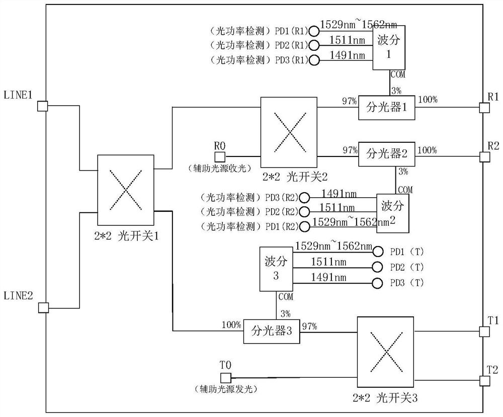
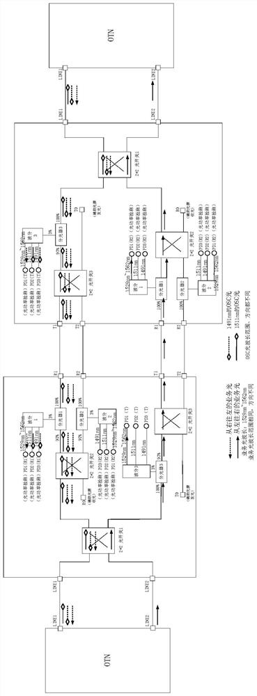
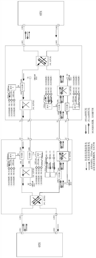
[0025] see figure 1 As shown, the present invention provides a double-ended switching optical fiber protection device suitable for an OTN network, two double-ended switching optical fiber protection modules, and each double-ended switching optical fiber protection module includes an optical interface LINE1, an optical interface LINE2, and a first optical switch. , second optical switch, third optical switch, first optical splitter, second optical splitter, third optical splitter, first wavelength division unit, second wavelength division unit, third wavelength division unit, auxiliary light source receiver R0 , auxiliary light source emitter T0, inlet end R1, inlet end R2, outlet end T1, outlet end T2;

[0026] The optical signal is transmitted through the optical interface LINE1 and the optical interface LINE2, the optical interface L...


PUM

PropertyMeasurementUnit
wavelengthaaaaaaaaaa

Abstract

The invention discloses a double-end switching optical fiber protection device suitable for an OTN network and a detection method, two double-end switching optical fiber protection modules are in mirror image connection to jointly form and work, and a first optical switch switches optical signals, so that the optical signals of an optical interface LINE1 and an optical interface LINE2 respectively pass through a third wavelength division unit, and the optical signals of the optical interface LINE1 and the optical interface LINE2 pass through a second wavelength division unit; the third wavelength division unit filters and separates the optical signals in different wavelength ranges, an optical power detector of the third wavelength division unit detects the power of the optical signals, and the directions and wavelengths of the optical signals on the optical interface LINE1 and the optical interface LINE2 are respectively determined by detecting the optical signals on the optical interface LINE1 and the optical interface LINE2; at the moment, the first optical switch is switched to enable optical signals to flow to correct optical fibers, meanwhile, the first wavelength division unit and the second wavelength division unit are provided with threshold values of different optical signals, namely, the range of optical power detected by the optical power detector, and when the power of the received optical signals exceeds the threshold values, full-automatic switching is achieved.

Description

technical field [0001] The invention relates to the technical field of optical communication, in particular to a double-ended switching optical fiber protection device and a detection method suitable for an OTN network. Background technique [0002] The traditional optical fiber line automatic switching protection device OLP is an automatic monitoring and protection system that is independent of the communication transmission system and completely built on the physical link of the optical cable. OLP is divided into 1+1 mode and 1:1 mode according to the different switching modes. The 1 mode adopts the principle of dual transmission and selective reception, the 1:1 mode adopts the principle of selective transmission and selection, and the 1:1 mode is divided into single-ended switching and double-ended switching. When the optical power value on the current working fiber is lower than the set switching threshold, an alarm prompt is issued and the standby fiber is automatically...

Claims


Application Information

Patent Timeline
Patent Type & Authority Applications(China)
IPC IPC(8): H04B10/25H04B10/66H04B10/67
CPCH04B10/25H04B10/675H04B10/66
Inventor 高贵阁伍建华汪涛
Owner NANJING XINTIANWEI PHOTOELECTRIC TECH
Learn More