Microphone circuit, microphone module and microphone sound pressure overload point lifting method
A microphone and circuit technology, applied to electrostatic transducer microphones, electrical components, electrostatic sensors, etc., can solve the problems of output sound distortion, microphone circuit linearity deterioration, and deterioration, so as to achieve good electrical signals and improve microphone sound Overload point, good effect of total harmonic distortion performance
- Summary
- Abstract
- Description
- Claims
- Application Information
AI Technical Summary
Problems solved by technology
Method used
Image
Examples
Embodiment 1
[0043] An embodiment of the present invention provides a microphone circuit 100 .
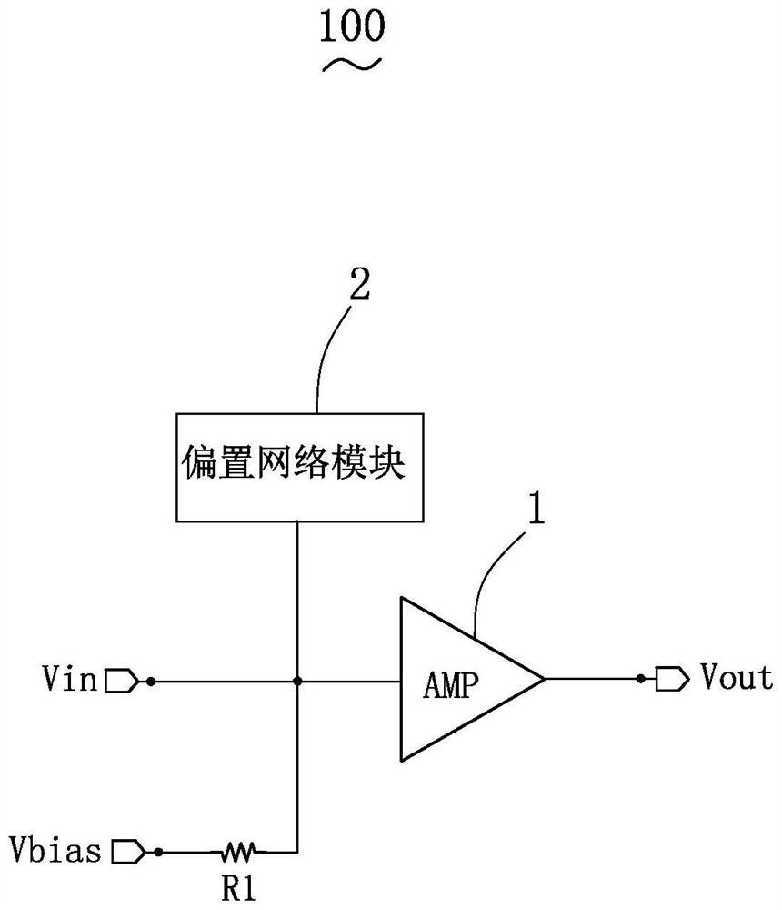
[0044] see figure 2 , figure 2 It is a schematic diagram of a circuit module of the microphone circuit of the present invention. The microphone circuit 100 includes an amplifier 1 , a bias resistor R1 and a bias network module 2 .
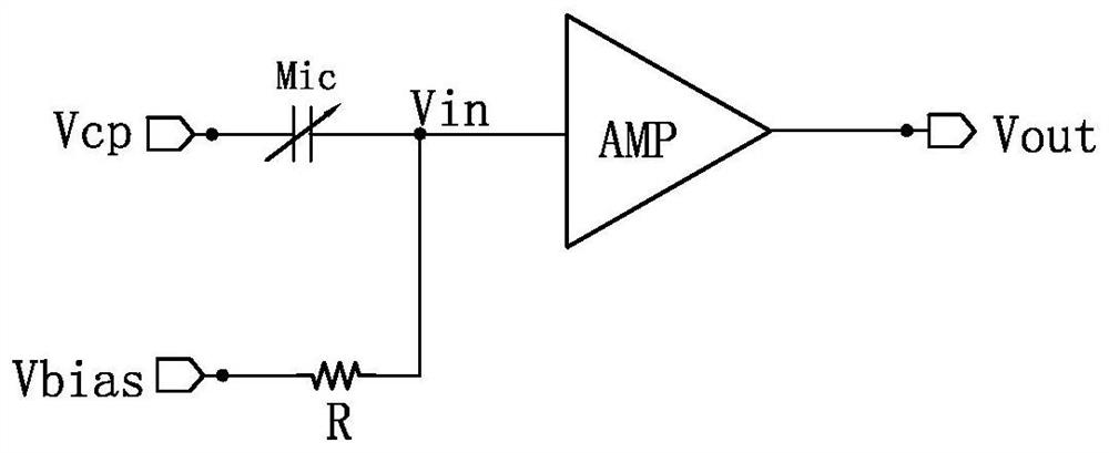
[0045] The amplifier 1 is used for receiving the signal Vin output by the external microphone Mic, and amplifying the signal Vin and outputting it.
[0046] The first end of the bias resistor R1 is used to connect to a preset bias voltage Vbias; the second end of the bias resistor R1 is used to connect to the output end of the microphone Mic, and the bias resistor R1 The second terminal of is connected to the input terminal of the amplifier 1. The input terminal of the amplifier 1 serves as the input terminal of the microphone circuit 100 . The output terminal of the amplifier 1 serves as the output terminal of the microphone circuit 100 .
[0047] The bias ...
Embodiment 2
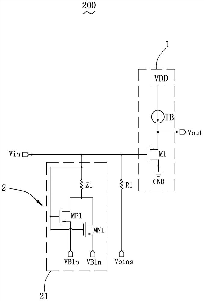
[0052] The second embodiment of the present invention provides a microphone circuit 200 . The microphone circuit 200 is a specific circuit of the microphone circuit 100 in the first embodiment.
[0053] see image 3 , image 3 It is a circuit diagram of the second embodiment of the microphone circuit 200 of the present invention.
[0054] The amplifier 1 includes a constant current source IB and a first transistor M1. The first transistor M1 is a PMOS transistor. In the second embodiment, the amplifier 1 is a source follower.
[0055] The input terminal of the constant current source IB is connected to the power supply voltage VDD.
[0056] The output terminal of the constant current source IB is connected to the source of the first transistor M1.
[0057] The source of the first transistor M1 and the output end of the constant current source IB serve as the output end of the microphone circuit 100 .
[0058] The gate of the first transistor M1 serves as the input termi...
Embodiment 3
[0070] The third embodiment of the present invention provides a microphone circuit 300 .
[0071] see Figure 4 , Figure 4 It is a circuit diagram of the third embodiment of the microphone circuit 300 of the present invention. The difference between the microphone circuit 300 and the microphone circuit 200 in the second embodiment is that: the bias network module 2 further includes an nth bias network circuit 2n, where n is a positive integer and satisfies: n≥2; The bias network circuit includes an nth PMOS transistor MPn, an nth NMOS transistor MNn and an nth impedance Zn.
[0072] The source of the nth PMOS transistor MPn is used to connect to the nth lower bias voltage VBnp, and the drain of the nth PMOS transistor MPn is respectively connected to the drain of the nth NMOS transistor MNn and the nth impedance Zn. first end.
[0073] The gate of the nth PMOS transistor MPn is used to connect to the input end of the microphone circuit, and the gate of the nth PMOS transi...
PUM
 Abstract
Description
Claims
Application Information
 - R&D
- Intellectual Property
- Life Sciences
- Materials
- Tech Scout
- Unparalleled Data Quality
- Higher Quality Content
- 60% Fewer Hallucinations
Browse by: Latest US Patents, China's latest patents, Technical Efficacy Thesaurus, Application Domain, Technology Topic, Popular Technical Reports.
© 2025 PatSnap. All rights reserved.Legal|Privacy policy|Modern Slavery Act Transparency Statement|Sitemap|About US| Contact US: help@patsnap.com


