Static elimination device based on chemical safety
A static elimination device, a safe technology, applied in the direction of static electricity, electrical components, transportation and packaging, etc., can solve the problems of uneven charge in the center and edge of the discharge area, poor elimination effect, and easy adhesion of dust on the surface of the device. Achieve the effect of avoiding uneven treatment and improving treatment efficiency
- Summary
- Abstract
- Description
- Claims
- Application Information
AI Technical Summary
Problems solved by technology
Method used
Image
Examples
Embodiment 1
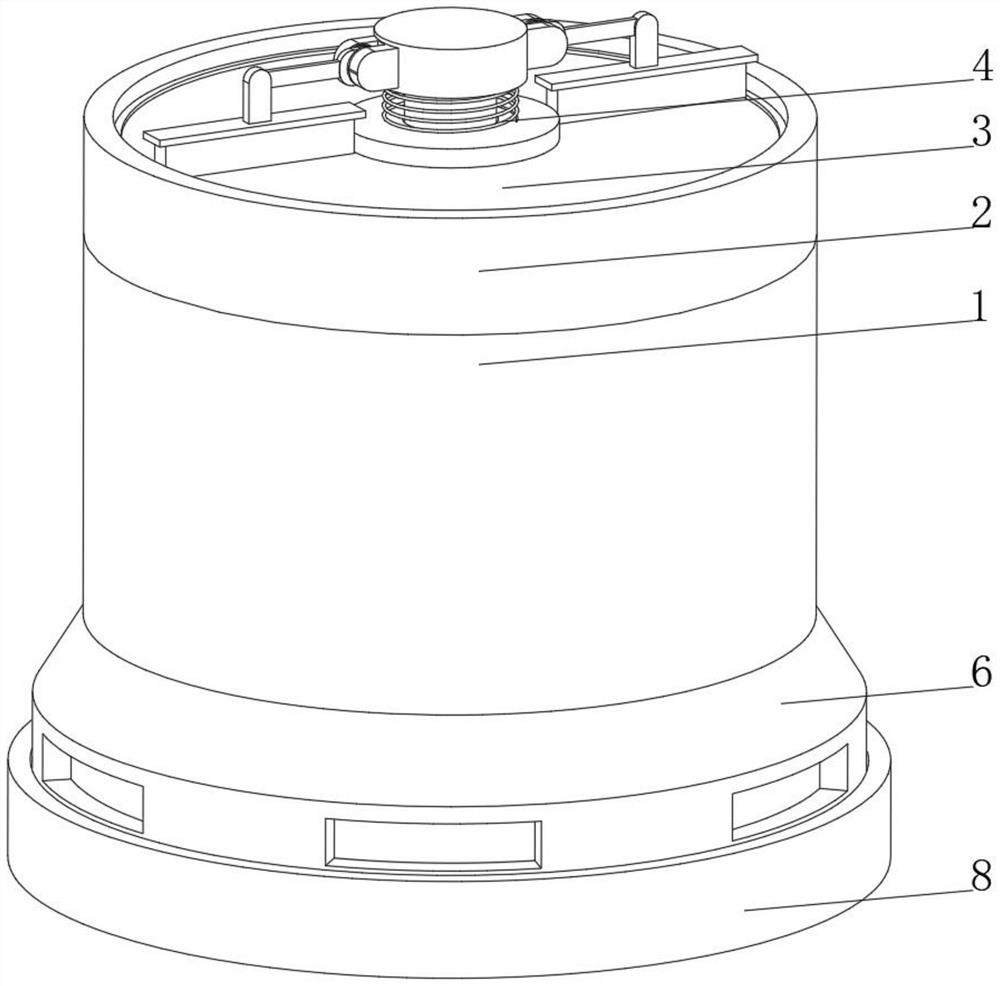
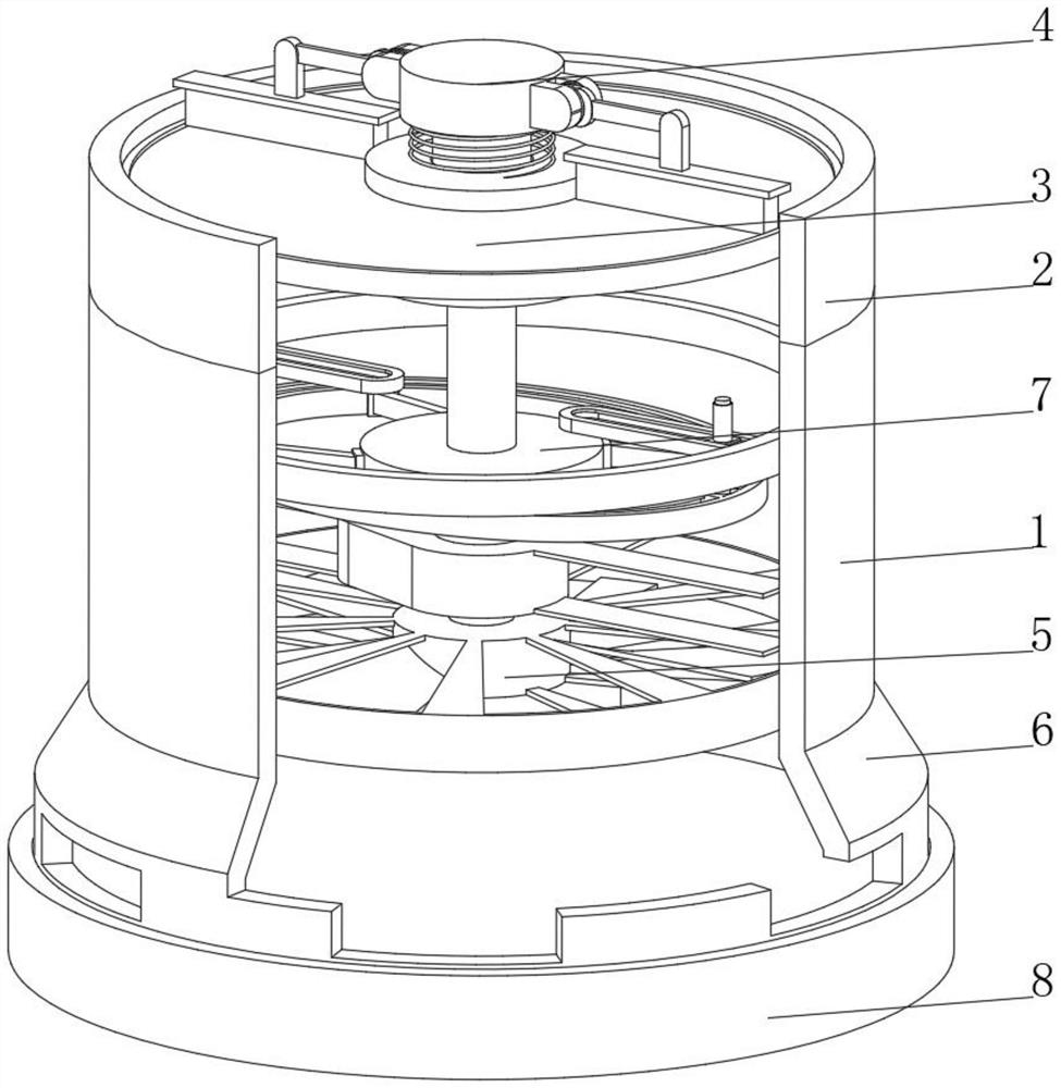
[0037] see Figure 1-Figure 3 , the present invention provides a technical solution: a static elimination device based on chemical safety, specifically including:
[0038] A processing cylinder 1, the top of the processing cylinder 1 is connected with an air inlet cylinder 2, and a filter screen 3 is fixedly connected to the top of the inner wall of the air inlet cylinder 2;
[0039] A cleaning device 4, the cleaning device 4 is arranged above the air inlet duct 2 and is fixedly connected to the central position of the filter screen 3;
[0040] Fan 5, the fan 5 is arranged at the bottom of the inner wall of the processing cylinder 1, the air outlet of the fan 5 is communicated with an air outlet 6, the side of the air outlet 6 is provided with an air outlet, and the air outlet on the side of the air outlet 6 is provided with multiple groups;
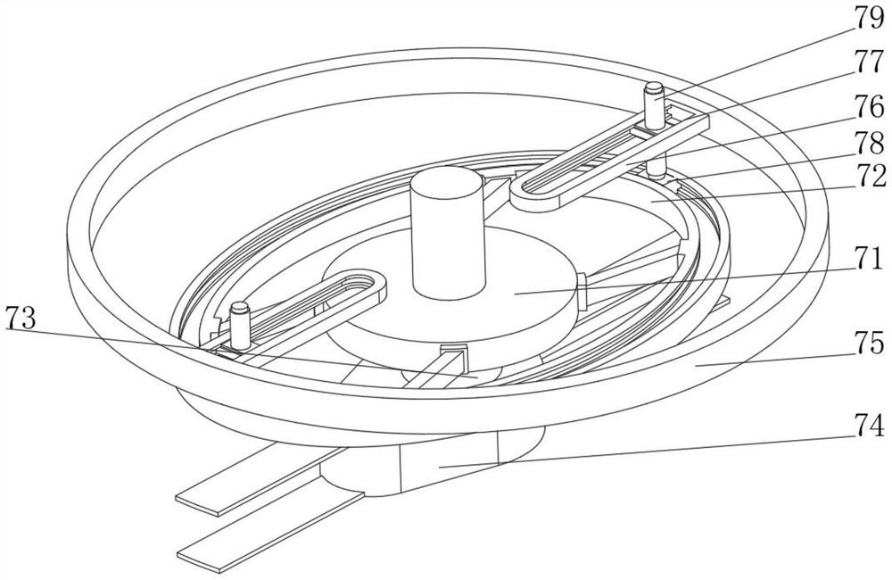
[0041] Elimination device 7, the elimination device 7 is arranged in the part between the filter screen 3 and the fan 5 inside the proce...
Embodiment 2
[0052] see Figure 1-Figure 5 , On the basis of the first embodiment, the present invention provides a technical solution: the cleaning device 4 includes a connecting sleeve 41, the inner wall of the connecting sleeve 41 is slidably connected with a block 42, and the top of the block 42 is fixedly connected with a rotating column 43, and the rotating column The top of 43 extends to the outside of the connecting sleeve 41 and is fixedly connected with a rotating block 44. The side of the rotating block 44 is fixedly connected with a cleaning brush 45. The bottom of the rotating block 44 is rotatably connected with a support spring 46, and the bottom of the support spring 46 is fixed with the top of the connecting sleeve 41. For connection, the inner part of the connecting sleeve 41 located below the block 42 is provided with a support rod 47, the top of the support rod 47 is fixedly connected with an arc-shaped clip 48, the bottom of the block 42 is provided with a word card slo...
Embodiment 3
[0054] see Figure 1-Figure 6 , on the basis of Embodiment 1 and Embodiment 2, the present invention provides a technical solution: the cleaning brush 45 includes a rotating seat 451, one side of the rotating seat 451 is provided with a rotating groove 452, and the inner wall of the rotating groove 452 is connected with a rotating bolt through a rotating bolt. Plate 453, one end of the rotating plate 453 extends to the outside of the rotating groove 452 and is fixedly connected with the brush head 454, the side of the rotating plate 453 is fixedly connected with a clockwork spring 455, and the side of the rotating seat 451 away from the rotating groove 452 is fixedly connected with the rotating block 44, The central end and the edge end of the clockwork spring 455 are respectively fixedly connected with the rotating plate 453 and the inner wall of the rotating groove 452, and a cleaning brush 45 is provided. The clockwork spring 455 pushes the rotating plate 453 to rotate throu...
PUM
 Abstract
Description
Claims
Application Information
 - R&D
- Intellectual Property
- Life Sciences
- Materials
- Tech Scout
- Unparalleled Data Quality
- Higher Quality Content
- 60% Fewer Hallucinations
Browse by: Latest US Patents, China's latest patents, Technical Efficacy Thesaurus, Application Domain, Technology Topic, Popular Technical Reports.
© 2025 PatSnap. All rights reserved.Legal|Privacy policy|Modern Slavery Act Transparency Statement|Sitemap|About US| Contact US: help@patsnap.com


