Flexible esophageal stent with nested structure

A nested structure and flexible technology, applied in the field of esophageal stents, can solve problems such as unsatisfactory support effect of esophageal stents, and achieve the effect of solving unsatisfactory support effect and strong applicability

Active Publication Date: 2022-07-05
SHIJIAZHUANG UNIVERSITY
View PDF11 Cites 0 Cited by
  • Summary
  • Abstract
  • Description
  • Claims
  • Application Information

AI Technical Summary

Problems solved by technology

[0006] The technical problem to be solved by the present invention is to provide a flexible esophageal stent with a nested structure to solve the problem of unsatisfactory supporting effect of the existing esophageal stent

Method used


Image

  • Flexible esophageal stent with nested structure
  • Flexible esophageal stent with nested structure
  • Flexible esophageal stent with nested structure

Examples


Embodiment 1

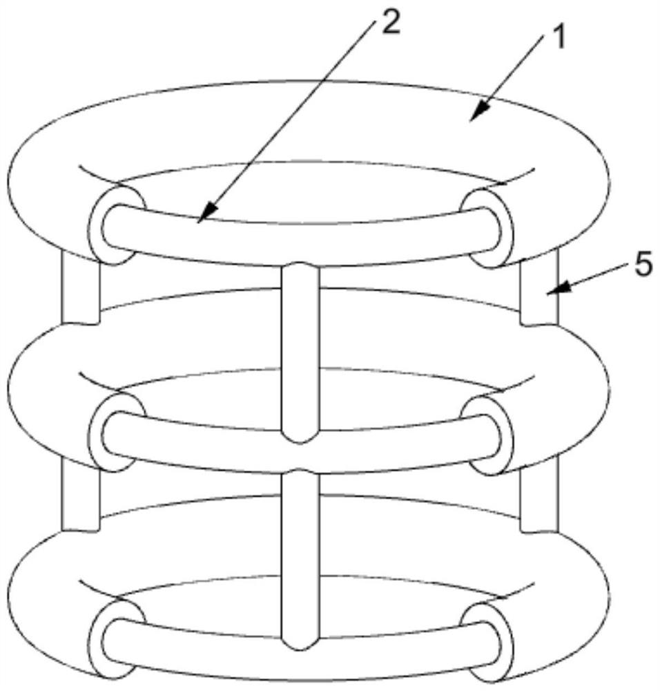
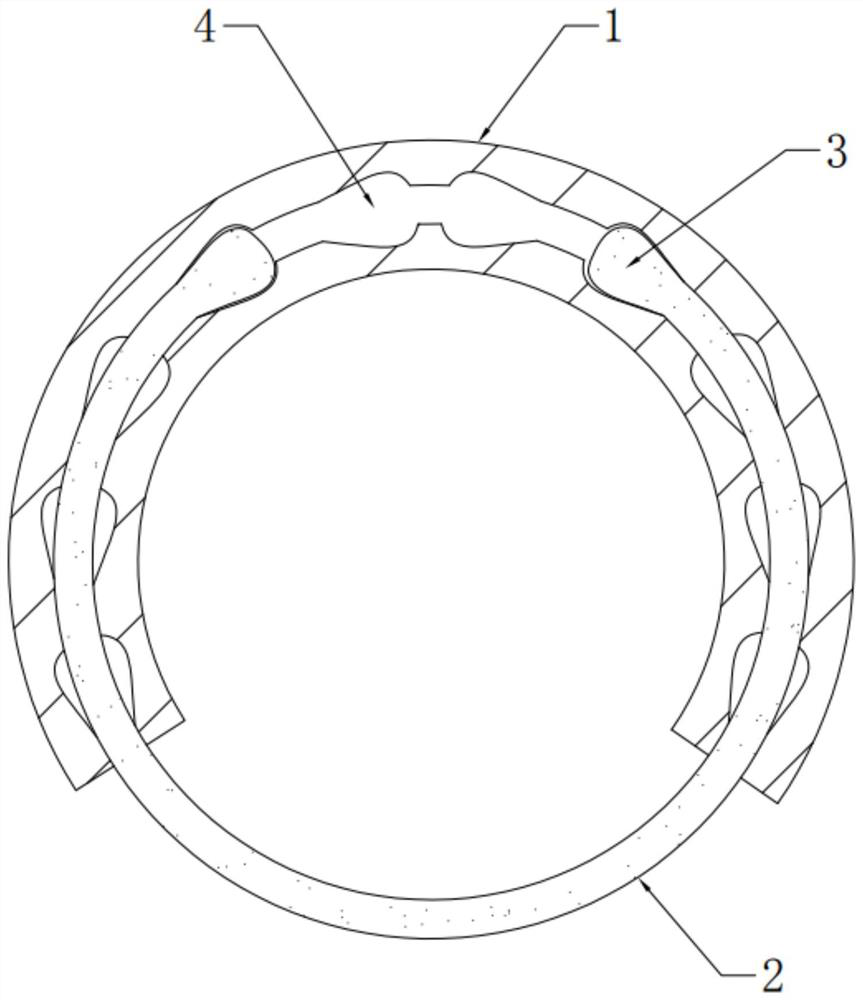
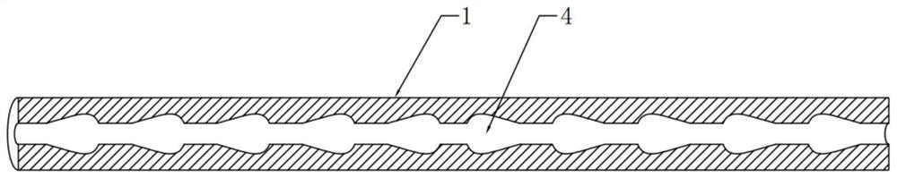
[0038] like Figure 1-Figure 4 As shown, a flexible esophagus stent with a nested structure includes a nested ring, and the nested ring includes a sleeve rod 1 and a connecting rod 2. The two ends of the connecting rod 2 are respectively provided with pear-shaped balls 3, and both ends of the connecting rod 2 are provided with pear-shaped balls 3 respectively. They are respectively connected with the small diameter ends of the pear-shaped balls 3, the pear-shaped balls 3 at both ends of the connecting rod 2 are respectively embedded in the two ends of the sleeve rod 1, and the two ends of the sleeve rod 1 are respectively provided with pear-shaped balls 3 suitable for The matching pear-shaped spherical cavity 4, the pear-shaped spherical cavity 4 is symmetrically distributed, the two ends of the sleeve rod 1 and the two ends of the connecting rod 2 are connected in a ring shape, and the sleeve rod 1 is provided with an embedding channel, and the embedding channel is along the s...

Embodiment 2

[0044] like Figure 5 and Image 6 As shown, the structure of this embodiment is roughly the same as that of Embodiment 1, and this embodiment is further optimized on the basis of Embodiment 1: the present invention also includes an adjusting sleeve, and the adjusting sleeve includes an outer cylinder 6 and a The inner cylinder 7, the inner cylinder 7 and the outer cylinder 6 are rotatably connected, the outer cylinder 6 and the inner cylinder 7 are provided with adjusting pliers, the adjusting pliers include a jaw and a hand-held part 11, and the jaws include an upper jaw 8 and a lower jaw 9 , the upper jaw 8 is arranged at one end of the inner cylinder 7 or the outer cylinder 6, the end of the upper jaw 8 away from the inner cylinder 7 or the outer cylinder 6 is rotatably connected with the lower jaw 9, and the lower jaw 9 is rotated close to the end of the inner cylinder 7 An adjusting rod 10 is connected, the adjusting rod 10 is inserted into the side wall of the inner cy...

Embodiment 3

[0051] like Figure 7 As shown, the structure of this embodiment is substantially the same as that of Embodiment 2, and this embodiment is further optimized on the basis of Embodiment 2: the adjusting rod 10 is sleeved with a spring 14, and the spring 14 is located in and / or inside the side wall of the outer cylinder 6 In the side wall of the cylinder 7 , one end of the spring 14 is fixedly connected with the outer cylinder 6 or the inner cylinder 7 , and the other end of the spring 14 is fixedly connected with the adjusting rod 10 .

[0052] Specifically, a spring 14 is sleeved on the adjusting rod 10 , and the spring 14 expands and contracts along the length direction of the adjusting rod 10 . There are two springs 14 , and the two springs 14 are located in the side wall of the outer cylinder 6 and the side of the inner cylinder 7 respectively. In the wall, one end of the spring 14 located in the outer cylinder 6 is fixedly connected with the outer cylinder 6, one end of the...


PUM


Abstract

The flexible esophageal stent with the nested structure comprises a nested ring, the nested ring comprises a sleeve rod and a connecting rod, pear-shaped balls are arranged at the two ends of the connecting rod respectively, the two ends of the connecting rod are connected with the small-diameter ends of the pear-shaped balls respectively, and the pear-shaped balls at the two ends of the connecting rod are embedded into the two ends of the sleeve rod respectively. Pear-shaped ball cavities matched with the pear-shaped balls are formed in the two ends of the sleeve rod respectively, the pear-shaped ball cavities are symmetrically distributed, an embedding channel is formed in the sleeve rod, the embedding channel penetrates through the sleeve rod in the length direction of the sleeve rod, the number of the pear-shaped ball cavities is at least two, the pear-shaped ball cavities are evenly distributed along the embedding channel, and the pear-shaped ball cavities are communicated. According to the esophageal stent, different numbers of nested rings are placed, the diameter size of each nested ring can be independently adjusted according to different esophageal stenosis degrees of patients, different positions of the esophagus are differentially supported, the applicability is high, and the problem that an existing esophageal stent is not ideal in supporting effect is effectively solved.

Description

technical field [0001] The invention belongs to the field of esophageal stents, and particularly relates to a flexible esophageal stent with a nested structure. Background technique [0002] Esophageal stents have a wide range of clinical applications in the treatment of esophageal diseases, and are often used to treat esophageal stenosis caused by esophageal cancer, refractory benign esophageal stenosis, postoperative anastomotic leakage, esophageal perforation, scar contracture stenosis after esophageal injury, and Solve problems such as acute esophageal variceal bleeding. [0003] At present, most of the esophageal stents in clinical use are made of metal materials. Generally, cylindrical and indistinguishable supports are provided to the key positions of the esophagus that need to be supported. Differential supports cannot be provided according to the stenosis of the esophagus, which will cause insufficient support in some parts or When the support is too strong, the su...

Claims


Application Information

Patent Timeline
Patent Type & Authority Applications(China)
IPC IPC(8): A61F2/04
CPCA61F2/04A61F2002/044
Inventor 马志刚安盼
Owner SHIJIAZHUANG UNIVERSITY
Why Eureka
Try Eureka