Cutting equipment capable of achieving rapid limiting and fixing and used for pipe machining
A technology of limit fixing and cutting equipment, which is applied in the direction of metal processing equipment, metal processing, shearing machine equipment, etc., can solve the problems of affecting cutting accuracy, affecting cutting efficiency, offset, etc., and achieve the effect of improving cutting efficiency
- Summary
- Abstract
- Description
- Claims
- Application Information
AI Technical Summary
Problems solved by technology
Method used
Image

Examples
Embodiment 1
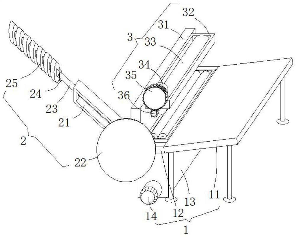
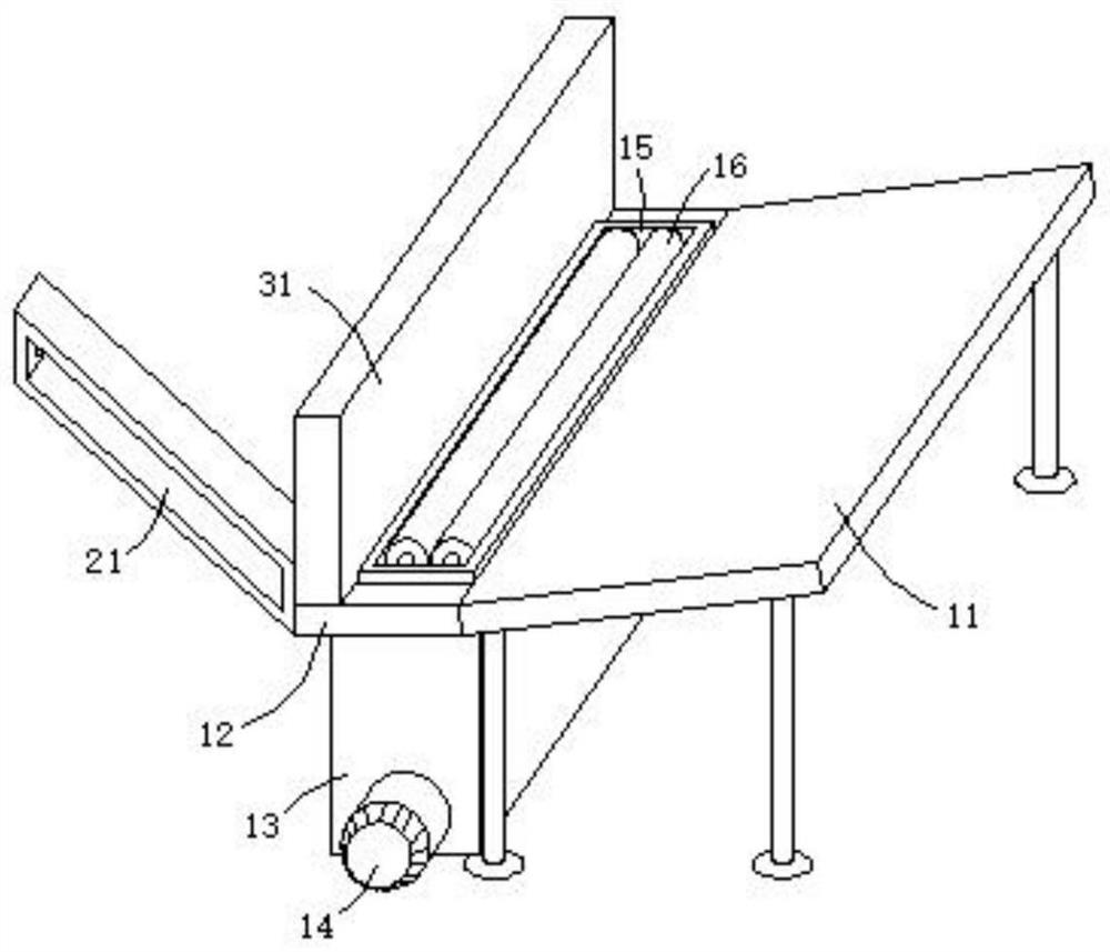
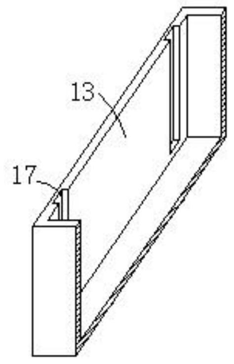
[0032] see figure 1 , figure 2 , Figure 4 and Image 6, this embodiment provides a fast limit and fixed pipe processing cutting equipment, including a support mechanism 1, a transmission mechanism 3 and a cutting mechanism 2, the support mechanism 1 includes a first support frame 12, a material placement plate 11 and a first motor 14. The material placement plate 11 is distributed obliquely, the first support frame 12 is fixedly arranged at the bottom end of the inclined surface of the material placement plate 11, and the first support frame 12 is distributed horizontally. The material placement plate 11 is inclined and distributed, so that the pipe material can automatically slide down to the horizontally distributed first support frame 12 along the inclined surface. There is no need to set up a power mechanism to transfer the pipe material, and no manual transmission operation is required, which helps to improve the cutting efficiency.
[0033] The first support frame 1...
Embodiment 2
[0040] see figure 1 , Figure 7 and Figure 8 , made further improvements on the basis of Example 1:
[0041] The cutting mechanism 2 includes a support beam 21, one end of the support beam 21 is fixedly arranged on the side wall of the end portion of the backing plate 31, and the other end of the supporting beam 21 is inclined to the side away from the backing plate 31. A rectangular hole, and a side wall of the rectangular hole close to the side wall of the backing plate 31 is rotated with a screw rod 26, the outer wall of the screw rod 26 is sleeved with a screw sleeve 23, and the outer wall of the screw sleeve 23 is close to the end of the screw rod 26. There are radially distributed connecting rods, the ends of the connecting rods are fixedly connected to the outer wall of the second motor 27, and the support beam 21 is inclined on the side wall of the backing plate 31, so the screw sleeve 23 and the screw rod 26 are both in an inclined state. When the end of the screw...
Embodiment 3
[0047] see figure 1 and Figure 5 , made further improvements on the basis of Example 2:
[0048] In order to improve the cutting efficiency, the transmission mechanism 3 includes a third motor 34. The third motor 34 is fixedly installed on the upper end side of the second support frame 32. The power shaft of the third motor 34 is connected with the first toothed plate 35. The second toothed plate 36 is fixedly connected to the second toothed plate 36 through the rotation of the pin shaft. The second toothed plate 36 meshes with the first toothed plate 35. During the cutting process, the third motor 34 can be used to drive the first toothed plate. 35 rotates, the rotating first toothed plate 35 can drive the second toothed plate 36 to rotate synchronously, and the rolling shaft 33 rotates, so as to drive the pipe to roll on the two supporting shafts 16, so that the cutting blade 22 can be cut along the outer wall of the pipe. Fully contact the cutting operation until cutting...
PUM
 Abstract
Description
Claims
Application Information
 - R&D
- Intellectual Property
- Life Sciences
- Materials
- Tech Scout
- Unparalleled Data Quality
- Higher Quality Content
- 60% Fewer Hallucinations
Browse by: Latest US Patents, China's latest patents, Technical Efficacy Thesaurus, Application Domain, Technology Topic, Popular Technical Reports.
© 2025 PatSnap. All rights reserved.Legal|Privacy policy|Modern Slavery Act Transparency Statement|Sitemap|About US| Contact US: help@patsnap.com