
Laser solder ball bonding device

A solder ball and laser technology, applied in welding equipment, metal processing equipment, manufacturing tools, etc., can solve the problems of expensive equipment, ball jamming, high processing accuracy and assembly requirements, reduce processing accuracy and difficulty, and increase ball feeding speed , the effect of saving time

Pending Publication Date: 2022-07-05
WUHAN BESKYS TECH CO LTD
View PDF1 Cites 0 Cited by
  • Summary
  • Abstract
  • Description
  • Claims
  • Application Information

AI Technical Summary

Problems solved by technology

[0003] There are two problems existing in this welding structure and operation process: one is that the machining accuracy and assembly requirements are very high, resulting in expensive equipment; Then it is necessary to disassemble the pump head for detailed cleaning of the pump head, which is time-consuming and complicated, which seriously affects the work of the system.
The device adopts a servo motor structure. Although it can effectively reduce the fault of ball jamming, it essentially transfers the horizontal position of the ball jamming in the turntable mode to the vertical position. There is still the problem of ball jamming, and even in the actual work process. empty ball phenomenon

Method used


Image

  • Laser solder ball bonding device
  • Laser solder ball bonding device
  • Laser solder ball bonding device

Examples


Embodiment Construction

[0030] The embodiments of the present invention are further described below with reference to the accompanying drawings, examples of which are shown in the accompanying drawings, wherein the same or similar reference numerals represent the same or similar elements or elements with the same or similar functions throughout. The embodiments described below by referring to the accompanying drawings are exemplary and are intended to be used to explain the present invention, but should not be construed as a limitation of the present invention, and any modifications, equivalent replacements, or Improvements, etc., should be included within the scope of the claims of the present invention, and those not described in detail in this technical solution are all known technologies.

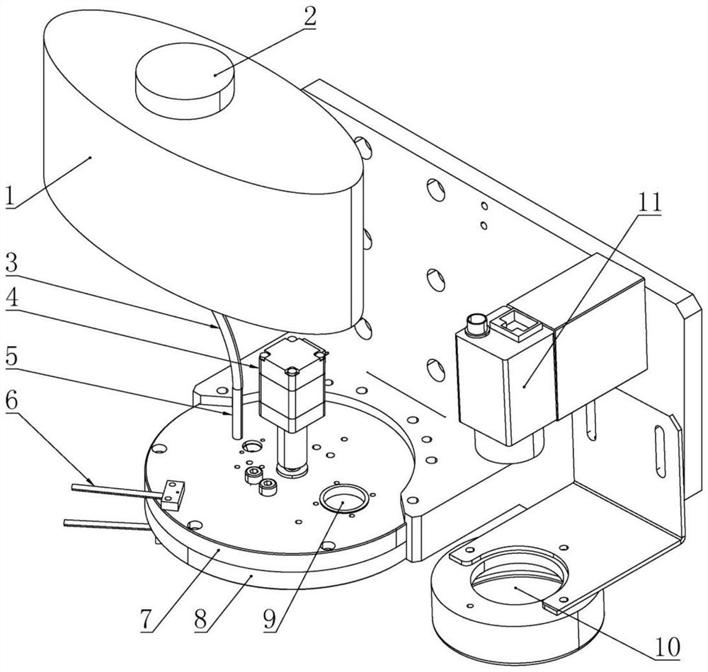
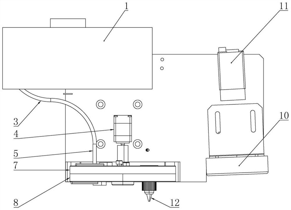
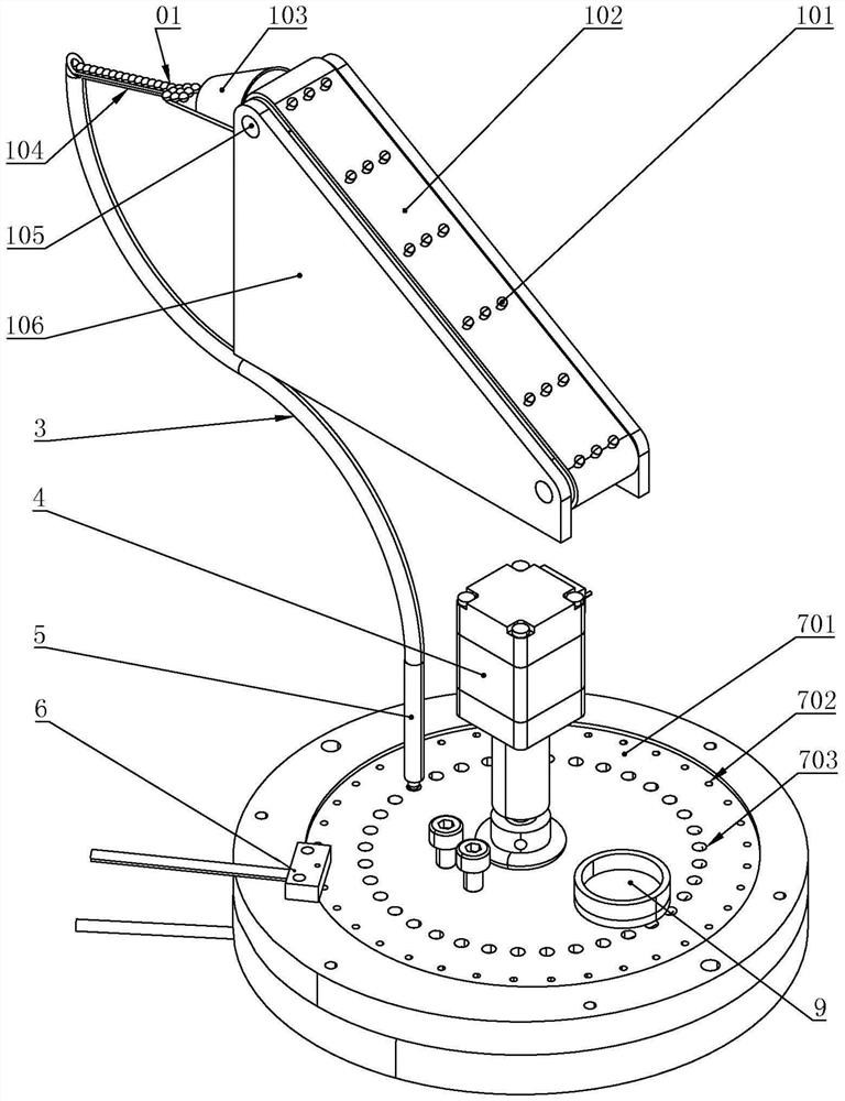
[0031] see figure 1 to the attached Figure 4 , The present invention is a laser tin ball welding device, including: a longitudinal granulation device, a disc granulation device, a tin melting device, and als...


PUM


Abstract

The invention designs a laser solder ball bonding device which comprises a longitudinal particle arranging device, a disc particle separating device and a tin melting device and further comprises a visual CCD and an illumination light source. A belt feeding mechanism is arranged in the stock bin, and solder balls are driven by a small hopper in the belt feeding mechanism to sequentially pass through a solder ball collector, a V-shaped groove and a transition pipe and finally form a row of solder ball particles which are sequenced in the vertical direction in a sequencing pipe. The disc grading device comprises a rotatable index plate and a position sensor, and the tin melting device comprises a laser incident port, a laser nozzle and a protective gas conveying device; the index plate is provided with a solder ball hole and a light hole, the solder ball hole receives a solder ball and transfers the solder ball to the laser nozzle, and then the solder ball is heated by laser in the protective gas atmosphere and melt-blown to a welding spot. The device can avoid ball clamping and empty situations, and is low in manufacturing cost, convenient to operate and easy to popularize and apply.

Description

technical field [0001] The invention relates to a laser tin ball welding device, which belongs to the technical field of laser welding. Background technique [0002] The solder ball laser welding system is mainly used in the 3C electronic industry, such as: camera module, VCM module, contact bracket, magnetic head and other precision and small components welding. In the existing solder ball welding machine structure, there are upper cover, The lower cover plate, the silo, and the upper and lower cover plates have a turntable, the turntable is driven by the motor to rotate around the central axis, the upper part of the turntable is evenly distributed with concentric small holes, the silo is fixed on the upper cover plate, The silo is provided with a round hole for accommodating tin balls rolling through. The round hole is butted with the small hole on the turntable, so that the tin ball enters the small hole on the turntable, and then the turntable rotates to drive the tin ba...

Claims


Application Information

Patent Timeline
Patent Type & Authority Applications(China)
IPC IPC(8): B23K1/005
CPCB23K1/0056
Inventor 徐琦王浩邱浩波喻露吴灿叶凯
Owner WUHAN BESKYS TECH CO LTD
Learn More