Road traffic guardrail welding installation equipment and method
A technology for road traffic and installation equipment, applied in welding equipment, welding equipment, auxiliary welding equipment, etc., can solve problems such as danger and low efficiency, unsatisfactory welding quality and efficiency, material movement and displacement, etc., to improve mobility performance , Improving the adaptive welding ability, improving the effect of quality and efficiency
- Summary
- Abstract
- Description
- Claims
- Application Information
AI Technical Summary
Problems solved by technology
Method used
Image
Examples
Embodiment 1
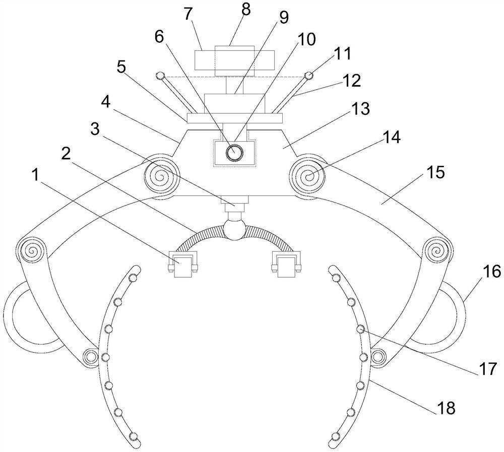
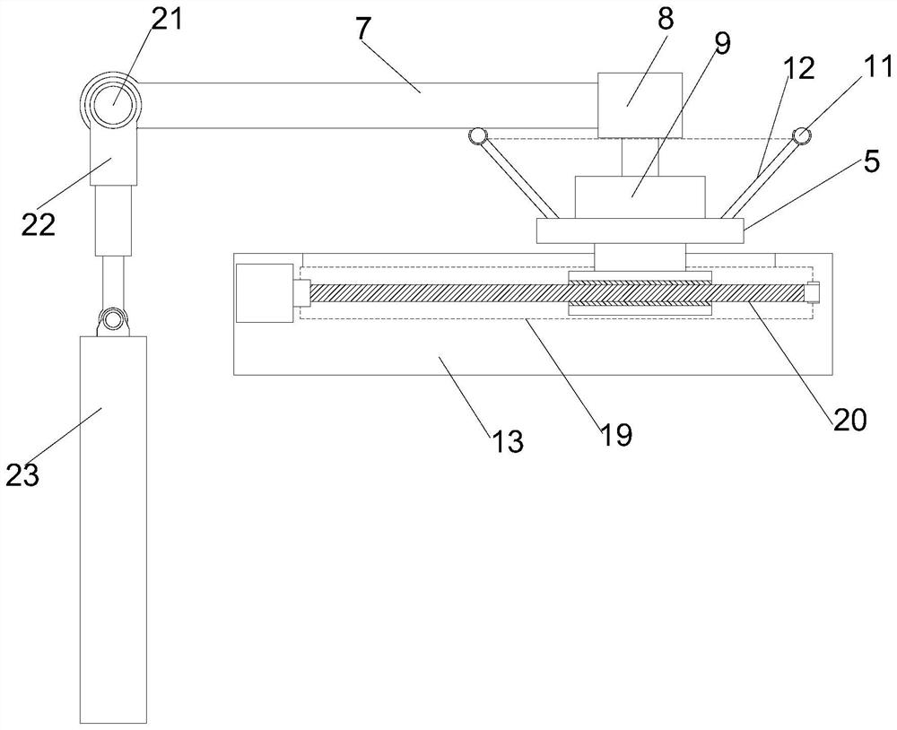
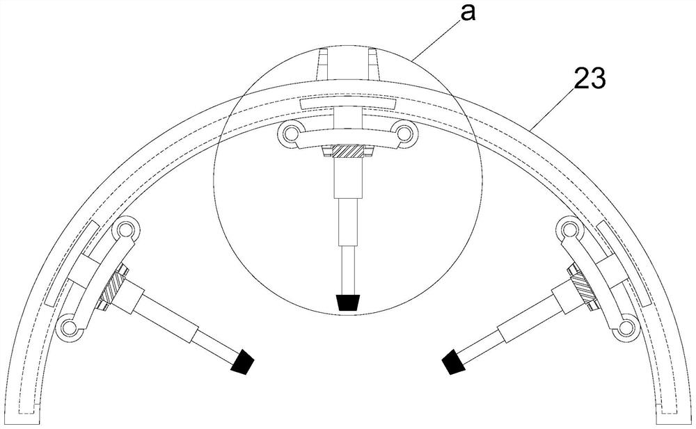
[0022] see figure 1 - image 3 , In the embodiment of the present invention, a road traffic guardrail welding installation equipment includes a support mounting plate 4, one side of the support mounting plate 4 is provided with a mobile mounting plate 5, one side of the mobile mounting plate 5 is provided with a steering motor 9, and the steering The outer end of the motor 9 is provided with a steering mounting column 8 through the rotating shaft, and a steering mounting plate 7 is provided on the outer side of the steering mounting column 8, and also includes: a clamping and moving mechanism, which is arranged on one side of the moving mounting plate 5 for installing the device on the On the guardrail; the displacement adjustment mechanism is arranged on the other side of the support mounting plate 4 for adjusting the angle and position; the sequential welding mechanism is arranged on the displacement adjustment mechanism for sequential welding.
Embodiment 2
[0024] see figure 1 In the embodiment of the present invention, the clamping and moving mechanism includes a reset shaft 14 symmetrically arranged at both ends of the support mounting plate 4. The reset shaft 14 is provided with two rotating mounting plates 15 in sequence, and the outermost rotating mounting plate 15 has an outer end. Both are provided with an elastic arc panel 18 through the rotating shaft, one side of the support mounting plate 4 is provided with an electronically controlled telescopic column 3, and the outer end of the electronically controlled telescopic column 3 is symmetrically provided with an elastic reset installation frame 2, and the elastic reset installation frame 2 The outer ends are provided with driving guide wheels 1 through the wheel frame, and the rotating mounting plates 15 on the same side are also rotatably connected by the reset rotating shaft 14. A number of moving balls 17 are arranged on the inner side;
[0025] Rotate the mounting pl...
Embodiment 3
[0027] see figure 1 , figure 2 , Figure 5 In the embodiment of the present invention, the displacement adjustment mechanism includes a guide installation groove 13 provided inside the support installation plate 4, the mobile installation plate 5 is connected with the guide installation groove 13 to connect a guide installation column 10, and the guide installation groove 13 is provided through the guide installation groove 13. There is a displacement stud 20, the guide mounting column 10 is provided with a displacement threaded hole 6 in cooperation with the displacement stud 20 passing through, and a displacement motor 19 is provided at one end of the supporting mounting plate 4 to match the displacement stud 20, and the displacement The adjustment mechanism also includes a rotating telescopic column 22, one end of which is connected to the outer end of the steering mounting plate 7 through the driving shaft 21, and one side of the moving mounting plate 5 is provided with ...
PUM
 Abstract
Description
Claims
Application Information
 - R&D
- Intellectual Property
- Life Sciences
- Materials
- Tech Scout
- Unparalleled Data Quality
- Higher Quality Content
- 60% Fewer Hallucinations
Browse by: Latest US Patents, China's latest patents, Technical Efficacy Thesaurus, Application Domain, Technology Topic, Popular Technical Reports.
© 2025 PatSnap. All rights reserved.Legal|Privacy policy|Modern Slavery Act Transparency Statement|Sitemap|About US| Contact US: help@patsnap.com


