
Automatic stacking and conveying equipment for plates

A conveying equipment and stacking technology, applied in the field of plate processing equipment, can solve the problems affecting the overall efficiency of plate processing, affecting the speed of stacking and transferring, and the offset of plate stacking positions, so as to achieve strong practicability, improve the degree of edge alignment, and improve efficiency effect

Pending Publication Date: 2022-07-05
广东易典智能设备有限公司
View PDF0 Cites 1 Cited by
  • Summary
  • Abstract
  • Description
  • Claims
  • Application Information

AI Technical Summary

Problems solved by technology

[0003] The existing technology has the following disadvantages: the plate parts formed on the forming equipment now use the mechanical arm to suck up the plates through the suction cup, and then stack them one by one. This operation requires a high degree of smoothness on the surface of the plates and is not applicable to all When the suction cup is lifted on the rough surface of the board, it is often because the surface of the board is not smooth enough that some of the suction cups cannot be sucked up, and it needs to be readjusted before sucking on the board, which affects the speed of stacking transfer. , due to the higher stacking, sometimes a slight error of the mechanical arm will cause the stacking position of the plate to shift more and more, the stability is not high, and it will seriously affect the overall efficiency of plate processing

Method used


Image

  • Automatic stacking and conveying equipment for plates
  • Automatic stacking and conveying equipment for plates
  • Automatic stacking and conveying equipment for plates

Examples


Embodiment Construction

[0029] The preferred embodiments of the present invention will be described below with reference to the accompanying drawings. It should be understood that the preferred embodiments described herein are only used to illustrate and explain the present invention, but not to limit the present invention.

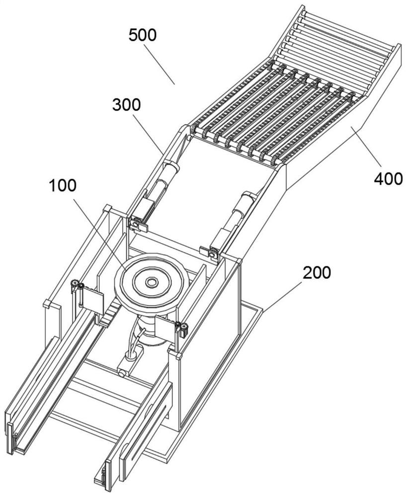
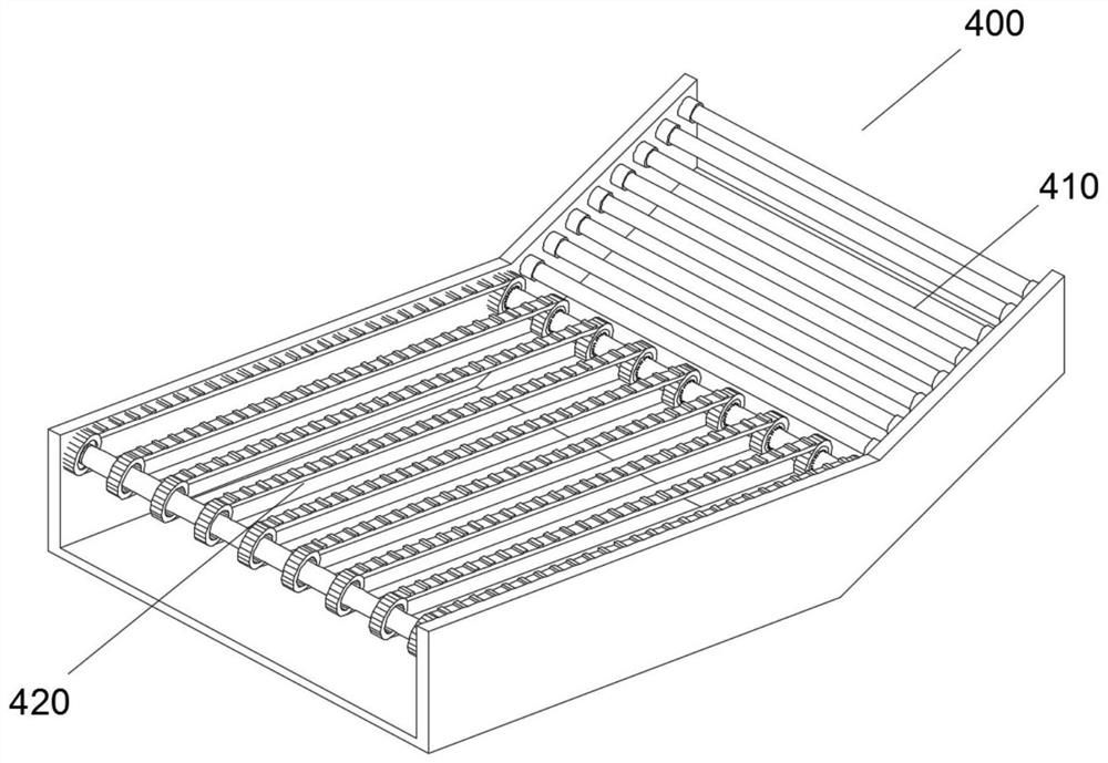
[0030] Refer to the attached Figure 1-8 , an automatic stacking and conveying equipment for plates provided by the present invention, in order to achieve the above purpose, the present invention provides the following technical solutions: an automatic palletizing and conveying equipment for plates, comprising an automatic palletizing and conveying equipment body 500, A climbing device 400 is installed on the right end of the main body 500 of the automatic palletizing and conveying equipment. The left end of the climbing device 400 is fixedly connected to the alignment device 300. The left end of the alignment device 300 is installed with a stacking device 200. It also includes ...


PUM


Abstract

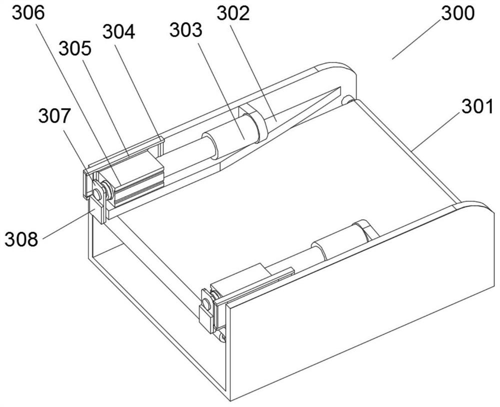
The invention discloses automatic stacking and conveying equipment for plates, and relates to the technical field of plate processing equipment.The automatic stacking and conveying equipment comprises an automatic stacking and conveying equipment body, a climbing device is installed at the right end of the automatic stacking and conveying equipment body, the left end of the climbing device is fixedly connected with an aligning device, and a stacking device is installed at the left end of the aligning device; a lifting device is installed on the inner wall of the bottom of the stacking device and further comprises a first roller conveying belt, one end of the first roller conveying belt is fixedly connected with a crawler belt conveying belt, the aligning device further comprises a second conveying belt, a centering plate is installed on the inner wall of one side of the aligning device, and the inner wall of one side of the aligning device is fixedly connected with an air cylinder. And a sliding rail is mounted on the inner wall of one side of the aligning device. The plate stacking device has the advantages that the plate stacking device is suitable for plates of different materials, the plates can be conveniently and automatically stacked, conveying is convenient, the aligning degree during stacking is improved, and the plate machining efficiency and stability are improved.

Description

technical field [0001] The invention relates to the technical field of sheet metal processing equipment, in particular to an automatic stacking and conveying equipment for sheets. Background technique [0002] As a common processing material in industrial manufacturing, plate parts are usually formed by cutting, stamping, extrusion and other processes. These processes can form plate parts at high speed, and the plate parts after high-speed forming need to be transferred to other processing equipment on the forming equipment. On the other hand, due to the light and thin structure of the plate parts, the plate parts are generally stacked in a stack, and then transferred to the processing equipment for continuous production operations. [0003] The existing technology has the following deficiencies: At present, the sheet pieces formed on the forming equipment mostly use a robotic arm to suck up the sheets through suction cups, and then stack them one by one. This operation requ...

Claims


Application Information

Patent Timeline
IPC IPC(8): B65G57/03B65G47/82B65G47/74B65G47/22B65G15/12B65G13/00
CPCB65G57/035B65G47/82B65G47/74B65G47/22B65G15/12B65G13/00Y02P70/10
Inventor 蓝溶青石伯雄陈文荣
Owner 广东易典智能设备有限公司
Learn More