[0035] In order to better explain the present invention and facilitate understanding, the present invention will be described in detail below with reference to the accompanying drawings and through specific embodiments.
[0036] In the present invention, unless otherwise expressly specified and limited, the terms "connected", "fixed" and the like should be understood in a broad sense, for example, "fixed" may be a fixed connection, a detachable connection, or an integrated; It can be a mechanical connection or an electrical connection; it can be a direct connection or an indirect connection through an intermediate medium, and it can be an internal communication between two elements or an interaction relationship between the two elements, unless otherwise explicitly defined. For those of ordinary skill in the art, the specific meanings of the above terms in the present invention can be understood according to specific situations.
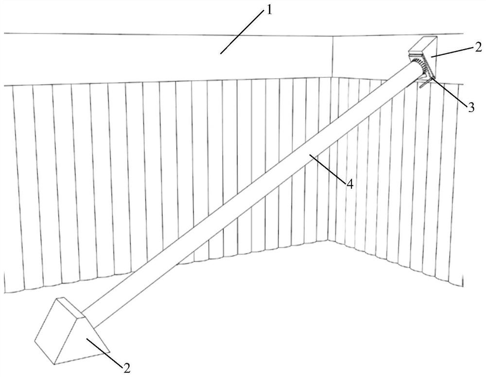
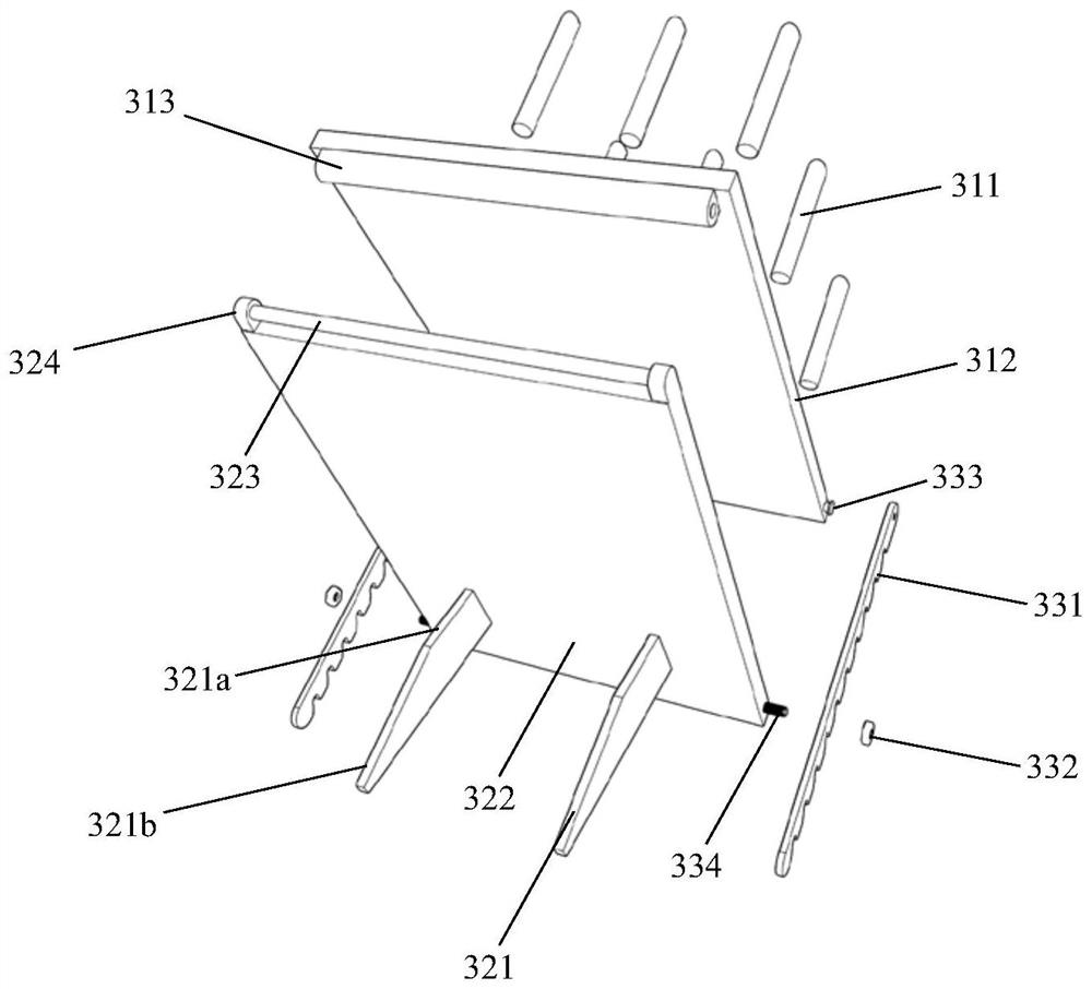
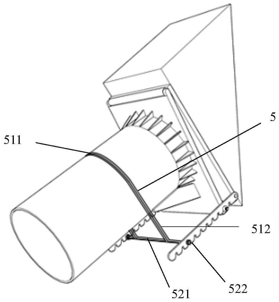
[0037] Please refer to Figure 1 to Figure 3 , the oblique throwing support inclination angle adaptation top support device disclosed in the present invention is applied to the oblique throwing support structure, and the oblique throwing support structure includes: a corbel support 2 fixed on the bottom of the foundation pit or on the waist beam 1 of the wall of the foundation pit; , The two ends are respectively fixed on the corbel support 2 of the throwing steel pipe 4. The oblique throwing inclination angle-adapting top supporting device 3 disclosed in the present invention is installed between the corbel support 2 and the throwing steel pipe 4 .
[0038] The tilt-angle-adapting top-supporting device 3 includes: a base plate 31 , an angle-adjusting clip support 33 and a support member 32 .
[0039] The base plate 31 is fixed on the corbel support 2 , the angle adjustment bracket 33 and the support member 32 are hinged on two sides of the base plate 31 respectively, and the support member 32 is relative to the The base plate 31 rotates, and the side edge of the support member 32 away from the base plate 31 is fixed on the angle adjustment bracket 33 , and the angle adjustment bracket 33 increases or decreases the relative relationship between the support member 32 and the angle adjustment bracket 33 . According to the inclination angle of the base plate 31 , the end surface of the throwing steel pipe 4 is attached to the supporting member 32 .
[0040] In the above-mentioned embodiment, the angle adjustment bracket 33, the base plate 31 and the support member 32 form a triangle between the corbel support 2 and the throwing steel pipe 4, and the base plate 31 is attached to the On the corbel support 2 , the support member 32 is attached to the end face of the thrown steel pipe 4 . The oblique throwing inclination angle-adapting top support device of the present invention is used to fit the corbel support 2 and the throwing steel pipe 4 respectively, so as to avoid the gap between the throwing steel pipe 4 and the corbel support 2 due to installation errors. From surface contact to edge contact, the support member 32 can effectively ensure that the contact with the throwing steel pipe 4 is end-face contact, and the operator can pass the actual installation process. Adjust the angle between the base plate 31 and the support member 32 to adjust the angle between the base plate 31 and the support member 32. After the adjustment, fix the angle adjustment bracket 33 between the base plate 31 and the support member 32, so as to realize the throwing of the steel pipe 4 and the corbel. The supports 2 are in surface contact, which eliminates the inclination error, prevents the throwing steel pipe 4 from being installed between the corbel supports 2 in the state of edge contact, and ensures the structural stability of the inclined throwing structure.
[0041]In the above-mentioned embodiment, the base plate 31 of the present invention includes: a base steel plate 312 and an implanted steel bar 311 . The base steel plate 312 is installed against the side of the corbel support 2 facing the throwing steel pipe 4 , and the implanted steel bar 311 passes through the base steel plate 312 and is embedded in the corbel support 2 in.
[0042] In the present invention, the corbel support 2 is formed by pouring concrete. When manufacturing the corbel support 2, the implanted steel bars 311 are inserted into the concrete. When the concrete is solidified and solidified to form the corbel support 2, the base steel plate is 312 is fixed on the corbel support 2 by the gripping force of the concrete to the implanted steel bar 311 .
[0043] The angle adjustment clamp 33 includes: a rotating shaft 333 , a screw 334 , a nut 332 and a clamp stay 331 . The rotating shaft 333 is disposed in the base plate 31 and exposed on both sides of the base plate 31 , and the card stay 331 is installed on both sides of the base plate 31 through the rotating shaft 333 . The card stay 331 can rotate relative to the base plate 31 . The screw rod 334 is disposed in the support member 32 and is located at an edge of the support member 32 away from the base plate 31 , and both ends of the screw rod 334 are exposed on both sides of the support member 32 .
[0044] When fixing the base plate 31 and the support member 32 , rotate the support member 32 to the target angle, and then fix it on the card stay 331 by the screws 334 on both sides of the support member 32 , after fixing, turn the nut 332 Tighten the screw rod 334 to stably fix the card stay 331 and the support member 32 .
[0045] Specifically, the card stay 331 is provided with a plurality of grooves 331a, and the screw rod 334 is fixed in the grooves 331a. The groove 331 a is disposed along the edge of the card stay 331 , and the groove 331 a is inclined toward one end of the rotating shaft 333 .
[0046] In the present invention, both ends of the throwing steel pipe 4 abut against the corbel support 2 or the supporting member 32, respectively, and the supporting member 32 is stressed toward the corbel support 2 and the supporting member 32. In the base plate 31, the groove 331a on the card stay 331 in the present invention is inclined to the rotating shaft 333, that is, one end of the base plate 31, which can effectively prevent the support member 32 from being separated from the groove 331a, and the throwing steel pipe 4 pushes The support member 32 can stably fix the screw rod 334 in the groove 331a.
[0047] The support member 32 includes: a support plate 322 and a wedge-shaped steel bracket 321 arranged on the support plate 322 . The wedge-shaped steel bracket 321 is perpendicular to the support plate 322 and is fixed on the side of the support plate 322 away from the base plate 31 , and the throwing steel pipe 4 is relative to the support plate through the wedge-shaped steel bracket 321 322 fixed.
[0048] In this embodiment, the wedge-shaped steel brackets 321 are used for the positioning of the throwing steel pipe 4 on the support plate 322 , and the throwing steel pipe 4 is abutted against the two wedge-shaped steel brackets 321 and fixed on the support plate 322 .
[0049] The wedge-shaped steel bracket 321 includes a vertical portion 321a and an inclined portion 321b, a plurality of end reinforcing ribs 41 are provided on the throwing steel pipe 4, and the inclined portion 321b abuts against the surface of the throwing steel pipe 4 and is inserted into the adjacent steel pipe 4. between the end reinforcing ribs 41 . The inclined portion 321b abutting on the throwing steel pipe 4 indicates that the end surface of the throwing steel pipe 4 is in contact with the surface of the support plate 322, and the inclined portion 321b can be effectively inserted between the adjacent end reinforcing ribs 41. The rotation of the throwing steel pipe 4 relative to the support plate 322 is avoided, so as to ensure the fixing stability of the throwing steel pipe 4 .
[0050] A hinge shaft 323 is provided on the edge of one side of the support plate 322 close to the base plate 31, and a hinge hole 313 is provided on the base plate 31; the hinge shaft 323 is inserted into the hinge hole 313 to make the support The plate 322 rotates relative to the base plate 31 .
[0051] In an achievable embodiment of the present invention, the support plate 322 is provided with lugs 324, and both ends of the hinge shaft 323 are fixed on the lugs 324. When the support plate 322 is installed on the base plate 31 , the lugs 324 are located on both sides of the hinge hole 313 .
[0052] In a preferred embodiment of the present invention, a plurality of fixing holes are provided on the side of the support plate 322 facing the throwing steel pipe 4 , and the fixing holes are provided on the wedge-shaped steel bracket 321 and the hinge shaft 323 In between, the bolts are fixed in the fixing holes and abut against the throwing steel pipes 4 , so that the throwing steel pipes 4 are fixed between the bolts and the wedge-shaped steel brackets 321 . The fixing hole is a screw hole, and the present invention can fix the throwing steel pipe 4 by matching the bolt and the wedge-shaped steel bracket 321 .
[0053] Please refer to Figure 4 , in a preferred embodiment of the present invention, the oblique throwing support device 3 further includes a fixing assembly 5, and the fixing assembly 5 includes an annular lock and a fixed shaft; the annular lock includes A semicircular annular portion 511 and extension portions 512 disposed at both ends of the annular portion 511, the fixed shaft member includes a fixed piece 521 and shaft ends 522 located at both ends of the fixed piece 521, and the shaft ends 522 are fixed On the angle adjustment bracket 33 , the annular portion 511 abuts against the throwing steel pipe 4 , and the extension portion 512 is inserted into the fixing piece 521 and fixed on the fixing piece 521 .
[0054] The fixing assembly 5 is used to fix the throwing steel pipe 4 and the angle adjustment bracket 33 . Since the throwing steel pipe 4 is against the wedge-shaped steel bracket 321 of the support plate 322 , the throwing steel pipe 4 is fixed by the fixing assembly 5 . 4 and the angle adjustment slot, which play the role of assisting the fixing of the throwing steel pipe 4.
[0055] In the present invention, a plurality of gear positions are set by adjusting the angle of the bracket 33 structure of the oblique throwing bracket to fit the top support device, and according to the difference in the inclination of the two sides of the corbel support, an appropriate gear position is selected, so that the four tops of the oblique throwing support steel pipe are The surface of the support plate 322 is in complete contact with the support surface of the support plate 322, so as to achieve the purpose of giving full play to the top support function of the oblique throwing support, ensuring the construction quality of the oblique throwing support structure, and at the same time avoiding the extension of the construction period caused by design changes and redoing.
[0056] It should be understood that the above description of the specific embodiments of the present invention is only to illustrate the technical route and characteristics of the present invention, and its purpose is to enable those skilled in the art to understand the content of the present invention and implement it accordingly, but the present invention Not limited to the specific embodiments described above. Any changes or modifications made within the scope of the claims of the present invention should be covered within the protection scope of the present invention.