Pressure testing machine

A technology of pressure testing and driving motors, applied in the direction of applying stable tension/pressure to test material strength, testing of mechanical components, testing of machine/structural components, etc., can solve problems such as contamination

Inactive Publication Date: 2022-07-05
南通尧成机械设备制造有限公司
View PDF4 Cites 2 Cited by
  • Summary
  • Abstract
  • Description
  • Claims
  • Application Information

AI Technical Summary

Problems solved by technology

[0004] The purpose of the present invention is to solve the shortcomings in the prior art, and propose a pressure testing machine. When the testing machine is in use, the product can be placed in the port for testing. After the test is completed, the port is rotated to The product will automatically fall when it is on the far left, so that there is no need to manually take the product away to avoid contamination of the product. At the same time, the dropped product will be pushed into the collection box by the push block to prevent the product from piling up under the placement table. After the product falls, The baffle can be brushed to avoid the residue of debris, thus ensuring the accuracy of the subsequent pressure test

Method used


Image

  • Pressure testing machine
  • Pressure testing machine
  • Pressure testing machine

Examples


Embodiment 1

[0032] refer to Figure 1-6 , a pressure testing machine, comprising a base 1, the upper end of the base 1 is provided with a plurality of support rods 3, the upper ends of the plurality of support rods 3 are jointly sleeved with a top plate 4, the top plate 4 is fixedly connected with the plurality of support rods 3, and the top plate The lower end of 4 is provided with a hydraulic rod 5, the telescopic end of the hydraulic rod 5 is fixedly connected with a pressing block 6, the lower end of the base 1 is installed with a driving motor 7, and the end of the output shaft of the driving motor 7 penetrates the base 1 and is fixedly connected with a first rotating rod 11 , the drive motor 7 drives the first rotating rod 11 to rotate 90 degrees each time, and then it can be closed. The upper end of the first rotating rod 11 is fixedly connected with a disk 12, and the disk 12 is provided with a plurality of ports 13, each of which is The side of the opening 13 close to the axis of...

Embodiment 2

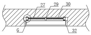
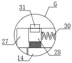
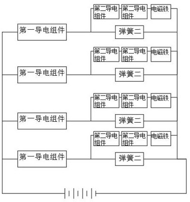
[0044] refer to Figure 7-11 The difference between this embodiment and Embodiment 1 is that the upper end of each telescopic groove 25 is provided with a brushing groove 27, and each brushing groove 27 is provided with a brushing assembly. The electromagnet 29 in the moving groove 27 is provided with two brushes 28 in the brushing groove 27. Each brush 28 is composed of a rectangular block and bristles. Each bristle is installed under the rectangular block. Made of iron material, the two brushes 28 are slidably connected to the inner wall of the brushing groove 27, and the adjacent surfaces of the two brushes 28 and the electromagnet 29 are elastically connected by springs 30. The upper end of each brush 28 is The inner top of the brushing groove 27 is provided with a conductive sheet 31 that cooperates with each other. The brushing groove 27 is communicated with the outside world through two blanking pipes 32. Each two matching conductive sheets 31 constitute a second conduc...


PUM


Abstract

The invention discloses a pressure testing machine which comprises a base, a driving motor is installed at the lower end of the base, the tail end of an output shaft of the driving motor penetrates through the base and is fixedly connected with a first rotating rod, the upper end of the first rotating rod is fixedly connected with a disc, and a plurality of through openings are formed in the disc. A telescopic groove is formed in the side, close to the axis of the disc, of each through opening, a baffle is arranged in each telescopic groove, and each baffle is slidably connected with the inner wall of the corresponding telescopic groove. A product can be placed in the through opening to be tested, the product can automatically fall off when the through opening rotates to the leftmost side after the test is finished, so that the product does not need to be manually taken away, the product is prevented from being polluted, meanwhile, the fallen product can be pushed into the collecting box by the push block, the product is prevented from being accumulated under the placing table, and the baffle can be brushed after the product falls off, so that the product is prevented from being damaged. And the condition of scrap residue is avoided, so that the accuracy of the subsequent pressure test is ensured.

Description

technical field [0001] The invention relates to the technical field of testing equipment, in particular to a pressure testing machine. Background technique [0002] At present, after the production of many products, it is necessary to carry out a reliability test, that is, a pressure test for this type of product. During the test, the product is often placed on a press, and a hydraulic rod is used to apply a certain Newton force on the product body. Observe Whether the function of the product has changed or whether the appearance of the product has changed to judge the quality of the product, however, the existing pressure testing machines still have the following problems in use: [0003] Most of the existing pressure testing machines manually place the product on the placing table of the pressure testing machine, and then manually remove the product after the test, and then place the new product on the placing table. This method has certain safety. Hidden danger, may be i...

Claims


Application Information

Patent Timeline
Patent Type & Authority Applications(China)
IPC IPC(8): G01N3/08G01N3/02G01M13/00B08B1/00
CPCG01N3/08G01N3/02G01M13/00B08B1/002G01N2203/0019
Inventor 黄晓龙
Owner 南通尧成机械设备制造有限公司
Why Eureka
Try Eureka