Intelligent isolating switch capable of being monitored on line

An isolating switch, intelligent technology, applied in the direction of electric switch, voltage/current isolation, air switch components, etc., can solve the problems of equipment melting and blowing, unable to obtain current size, isolating switch temperature monitoring, heating, etc., to reduce Equipment cost, the effect of realizing real-time monitoring and abnormal warning

Pending Publication Date: 2022-07-05
广东菲利特电气科技有限公司
View PDF1 Cites 0 Cited by
  • Summary
  • Abstract
  • Description
  • Claims
  • Application Information

AI Technical Summary

Problems solved by technology

[0004] However, the above technical solutions cannot obtain functions such as current magnitude and operating temperature monitoring of isolating switches, and cannot meet the needs of transparent power grids and ubiquitous power Internet of Things
However, the high-voltage isolating switch has been working under the condition of high voltage and high current. Even if the contact resistance increases slightly, the power loss of the contact will increase and generate heat. If the heat is not treated in time, the equipment may be melted down. Serious Consequences of Burnout

Method used


Image

  • Intelligent isolating switch capable of being monitored on line
  • Intelligent isolating switch capable of being monitored on line
  • Intelligent isolating switch capable of being monitored on line

Examples


Embodiment Construction

[0028] The specific embodiments of the present invention will be described in further detail below with reference to the accompanying drawings and embodiments. The following examples are intended to illustrate the present invention, but not to limit the scope of the present invention.

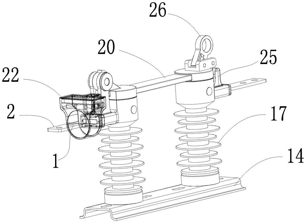
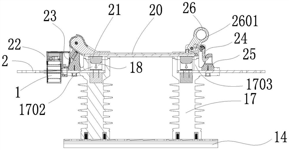
[0029] like Figure 1-4 As shown, an intelligent disconnecting switch that can be monitored online includes:

[0030] The base 14, the two ends of the base 14 are fixed with insulators 17;

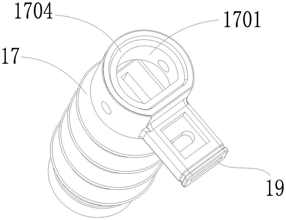
[0031] Insulator 17, such as figure 2 and 3 As shown, the upper end of the insulator 17 is provided with a sealing cavity 1701, a static contact 18 is fixed in the sealing cavity 1701, and an opening 19 through which the conductive strip 2 can be inserted is opened on one side of the sealing cavity 1701;

[0032] Knife 20, such as Figure 1-3 As shown, the blade 20 is arranged above the insulator 17 to be hinged with the insulator 17, and a movable contact 21 corresponding to the static contact 18 is ...


PUM


Abstract

The invention discloses an intelligent disconnecting switch capable of being monitored on line, which is characterized by comprising a base, and insulators are fixedly arranged at the two ends of the base; the upper end of the insulator is provided with a sealing cavity, a static contact is fixedly arranged in the sealing cavity, and one side of the sealing cavity is provided with an opening into which the conductive strip can be inserted; the knife switch is arranged above the insulator and is hinged with the insulator, and a moving contact corresponding to the static contact is arranged below the knife switch; the monitoring device is arranged on one side of the insulator, and the monitoring device comprises a shell, and a current transformer, a power supply module and a monitoring module which are arranged in the shell. Compared with the prior art, the intelligent isolating switch has the following advantages: on one hand, the intelligent isolating switch realizes a fully-closed structure of dynamic equipment, and a product does not have any exposed electrified body; the short circuit problem caused by ice, snow, rainwater, strong wind, birds and beasts and the like is solved; on the other hand, the current magnitude and the operating state and temperature of the isolating switch can be accurately and remotely acquired through the monitoring device, and the requirements of a transparent power grid and ubiquitous power internet of things can be met.

Description

technical field [0001] The invention relates to the technical field of power equipment, in particular to an intelligent isolation switch that can be monitored online. Background technique [0002] The main function of the isolation switch is to form an obvious disconnection point in the circuit, which is generally used for isolating the power supply, switching off operation, or turning on and off small current circuits. In outdoor AC 50~60Hz and rated voltage 6~10kV power distribution system, the enclosed disconnect switch can be used directly as power isolation. Therefore, the outdoor AC high voltage enclosed disconnect switch is one of the main equipment in the outdoor AC high voltage distribution system. . [0003] The Chinese Patent Publication No. CN110212644A discloses a system and method for monitoring the working state of an isolating switch, including a controller and a state monitoring device; the state monitoring device includes an image acquisition device, an el...

Claims


Application Information

Patent Timeline
Patent Type & Authority Applications(China)
IPC IPC(8): H01H31/02H01H9/04H01H9/16H01H9/52G01R31/327G01R15/18G01K7/18
CPCH01H31/02H01H9/04H01H9/16H01H9/52G01R31/327G01R15/18G01K7/18
Inventor 陈荣生
Owner 广东菲利特电气科技有限公司
Why Eureka
Try Eureka