Clamp head of bipolar electrocoagulation clamp

A technology of electrode and forceps head, applied in the field of forceps head of bipolar electrocoagulation forceps, can solve the problems of hidden danger, high-frequency discharge in cavity, short service life, etc., to improve safety, improve safety performance, and connect firmly Effect

Pending Publication Date: 2022-07-08
ZHEJIANG TIANSONG MEDICAL INSTR
View PDF0 Cites 1 Cited by
  • Summary
  • Abstract
  • Description
  • Claims
  • Application Information

AI Technical Summary

Problems solved by technology

[0003] However, at present, the insulator is embedded in the upper clamp rod in the clamp head of the bipolar electrocoagulation forceps, and a mounting hole is penetrated on the upper clamp rod and the insulator inside, and the lower clamp rod is fixed with a ceramic pin , and the ceramic pin is passed through the mounting hole on the upper clamping rod and its inner insulating part, and can rotate in the mounting hole, and since there is a gap between the ceramic pin and the mounting hole, and the upper clamping rod is a conductor, The lower clamping rod is also a conductor, so it is easy to generate a space discharge problem between the upper clamping rod and the lower clamping rod through the gap between the ceramic pin and the mounting hole. At the same time, one of the clamp heads of the existing bipolar electrocoagulation forceps The clamping rod is hinged with an electrically conductive mounting base, but the mounting base has a cavity near the clamping rod, and since the tail end of the clamping rod will extend into the cavity to connect with the conductive core , it will easily lead to the problem of high-frequency discharge in the cavity, so there is a big safety hazard in the work of the bipolar coagulation forceps in the prior art in the environment of the liquid in the peritoneal cavity of the human body
[0004] Moreover, since the insulator of the clamp head of the bipolar electrocoagulation forceps in the prior art is embedded in the upper clamping rod, the insulating part is easy to float in the upper clamping rod, resulting in the bipolar electrocoagulation forceps in the prior art The pincer head of the bipolar electric coagulation forceps is not firm, and the pin used to make the two pincer bars hinged in the prior art is a ceramic pin, which is easy to break. Therefore, the pincer head of the bipolar electrocoagulation forceps in the prior art is easily damaged, and the service life is longer short

Method used


Image

  • Clamp head of bipolar electrocoagulation clamp
  • Clamp head of bipolar electrocoagulation clamp
  • Clamp head of bipolar electrocoagulation clamp

Examples


Embodiment Construction

[0043] The technical solutions in the embodiments of the present invention will be clearly and completely described below with reference to the accompanying drawings in the embodiments of the present invention. Obviously, the described embodiments are only a part of the embodiments of the present invention, rather than all the embodiments. Based on the embodiments of the present invention, all other embodiments obtained by those of ordinary skill in the art without creative efforts shall fall within the protection scope of the present invention.

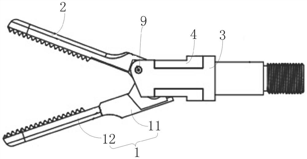
[0044] The embodiment of the present invention discloses a forceps head of a bipolar electrocoagulation forceps, comprising:

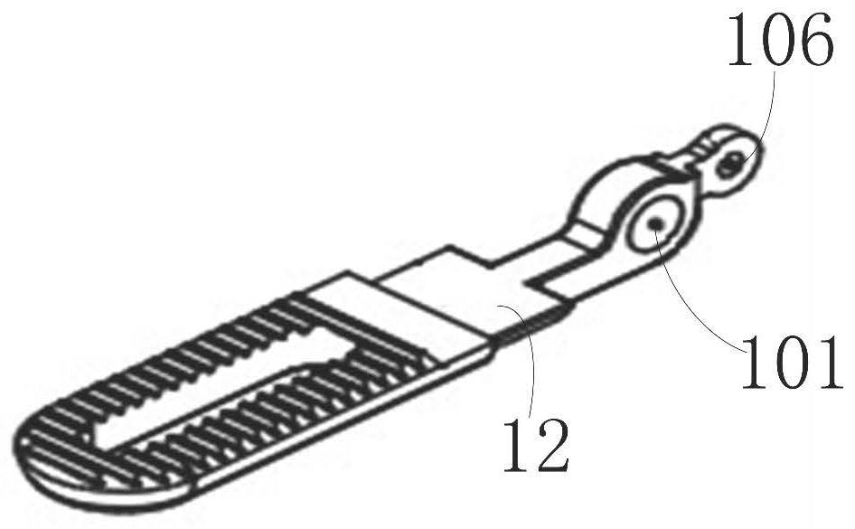
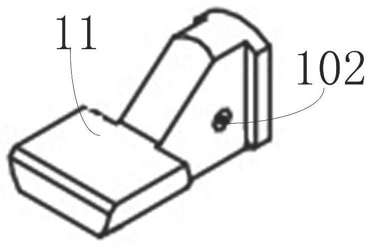
[0045] The first clamp rod 1 is integrally connected by an insulating member 11 and a metal clamp rod 12 having a through hole 101, and the insulating member 11 is covered on the metal clamp rod 12, and the metal clamp Both ends of the rod 12 extend beyond the insulating member 11, and the insulating member 1...


PUM


Abstract

A first forceps holder rod is integrally connected by an insulating part and a metal forceps holder rod provided with a through hole in a penetrating manner, a first mounting hole coaxially distributed with the through hole is formed in the position, corresponding to the through hole, of the insulating part in a penetrating manner, and the hole wall of the through hole is coated with the hole wall of the first mounting hole; a first pin shaft is fixed at the tail end of the second forceps holder rod, is arranged in the first mounting hole in a penetrating manner and can rotate in the first mounting hole; a first U-shaped slot is formed in the head end of the conductive fork piece, and the two side walls of the first U-shaped slot are hinged to the tail end of the second forceps holder rod; the insulating fork piece is connected in the first U-shaped slot, the head end of the insulating fork piece is provided with a second U-shaped slot, and the tail end of the insulating piece can respectively define an insulating space with two side walls of the second U-shaped slot and the slot bottom of the second U-shaped slot. According to the clamp head of the bipolar electrocoagulation clamp, space discharge is not prone to being generated, so that the safety performance of the clamp head is improved, and meanwhile the service life of the clamp head is prolonged.

Description

technical field [0001] The invention relates to the technical field of surgical forceps for medical instruments, in particular to a forceps head of a bipolar electrocoagulation forceps. Background technique [0002] Electrocoagulation forceps are a kind of commonly used medical equipment, which are mostly used in brain surgery, microsurgery, ENT, obstetrics and gynecology and hand surgery. Electrocoagulation for hemostasis by bipolar conduction. The application method is: providing high-frequency electric energy to the body tissue through the two tips of the bipolar, so that the tissue between the two ends of the bipolar is dehydrated and coagulated, so as to achieve the purpose of hemostasis. [0003] However, at present, the insulator is embedded in the upper clamp rod in the clamp head of the bipolar coagulation forceps, and the upper clamp rod and the insulator in it are provided with installation holes, and the lower clamp rod is fixed with a ceramic pin. , and the ce...

Claims


Application Information

Patent Timeline
Patent Type & Authority Applications(China)
IPC IPC(8): A61B18/12A61B18/14
CPCA61B18/12A61B18/1445A61B2018/00589A61B2018/0091
Inventor 徐斌峰徐斌顶舒明泉方秋红赵卓
Owner ZHEJIANG TIANSONG MEDICAL INSTR
Why Eureka
Try Eureka