Microfluidic chip

A technology of microfluidic chips and flow channels, applied in the field of microfluidics, can solve the problems of inability to apply small micro-droplets, complex device structures, and lack of universality, and achieve accurate and controllable incubation time, simplify Effects of Chip Structure and Extended Incubation Time

Pending Publication Date: 2022-07-08
SHENZHEN HUADA GENE INST
View PDF0 Cites 0 Cited by
  • Summary
  • Abstract
  • Description
  • Claims
  • Application Information

AI Technical Summary

Problems solved by technology

Among them, the array device and the branch device design a special column or branch structure in the microchannel, and use the change of flow velocity and pressure in the microchannel to capture the droplet, so that the droplet is still in the device for incubation. However, the column in the array device The size of the micro-droplets needs to match the corresponding size of the micro-droplets, there is no universality, and the micro-droplets captured by the branched device will also be limited by the device structure
The height difference device needs to design complex height changes in the device to slow down the flow velocity of the micro-droplets to achieve the purpose of incubation. However, this leads to a complex structure of the device itself and cannot be applied to small-sized micro-droplets.
The tandem slit device traps droplets through a channel that matches the shape of the microdroplets to achieve the purpose of incubation and observation. However, the design of the channel needs to match the microdroplets of the corresponding size, which is also not universal.

Method used


Image

  • Microfluidic chip
  • Microfluidic chip
  • Microfluidic chip

Examples


Embodiment Construction

[0089] In order to further illustrate the technical means and effects adopted by the present application to achieve the intended purpose of the invention, the following detailed descriptions are made on the specific embodiments, structures, features and effects of the present application in conjunction with the accompanying drawings and preferred embodiments.

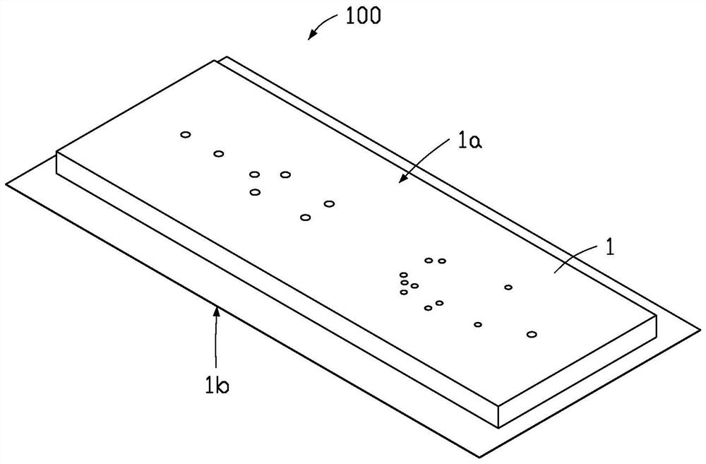
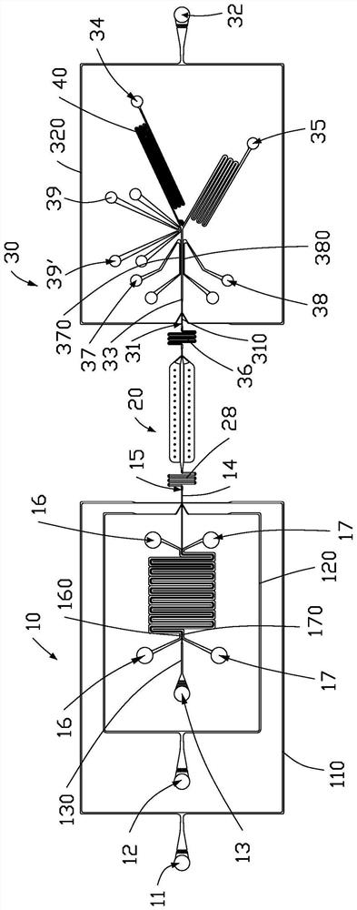
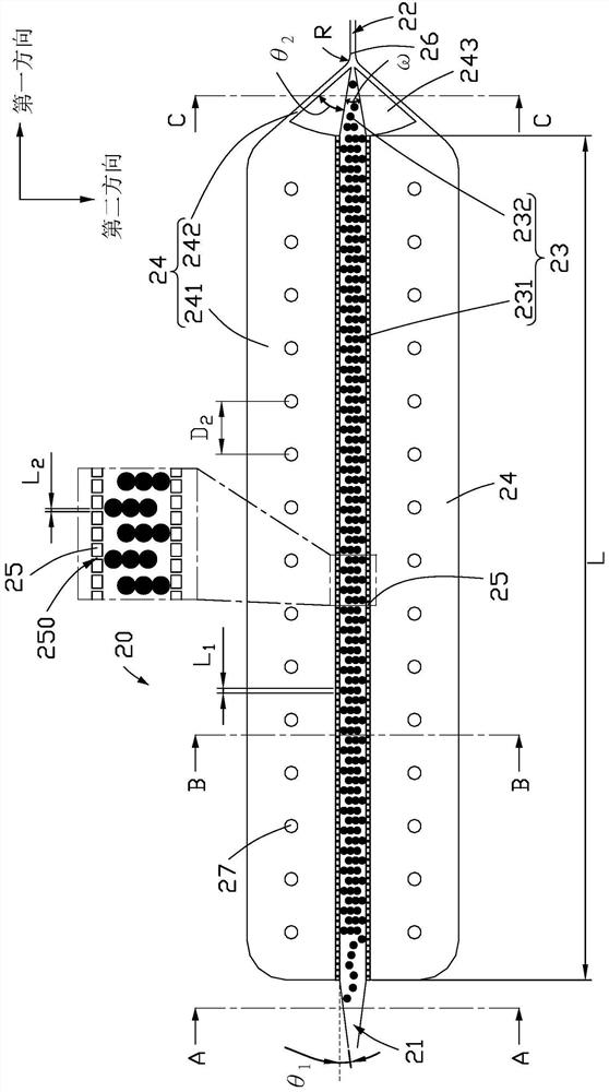
[0090] see figure 1 and figure 2 , an embodiment of the present application provides a microfluidic chip 100 including a chip body 1 . The chip body 1 includes a base 1a and a cover 1b disposed on the base 1a. A droplet generating module 10 , a droplet incubation module 20 and a droplet sorting module 30 are arranged on the substrate 1a. The droplet incubation module 20 is connected between the droplet generation module 10 and the droplet sorting module 30 . In one embodiment, the droplet generation module 10, the droplet incubation module 20 and the droplet sorting module 30 are arranged in the same direction.

[...


PUM

PropertyMeasurementUnit
particle diameteraaaaaaaaaa
heightaaaaaaaaaa

Abstract

The micro-fluidic chip comprises a liquid drop inlet, a liquid drop outlet, a liquid drop incubation channel, a continuous phase channel and a confluence channel. The liquid drop incubation channel is connected with the liquid drop inlet and is used for allowing a continuous phase and a plurality of liquid drops carried by the continuous phase to flow into the liquid drop incubation channel; the continuous phase channel is positioned on at least one side of the liquid drop incubation channel and is communicated with the liquid drop incubation channel through the opening, so that the continuous phase enters the continuous phase channel through the opening after being separated from the liquid drop, and the liquid drop is incubated in the liquid drop incubation channel. And the continuous phase channel and the liquid drop incubation channel are intersected at the confluence channel, so that the continuous phase and the incubated liquid drops are converged again at the confluence channel. The liquid drop outlet is connected with the confluence channel. According to the invention, the purposes of droplet incubation and observation are achieved, and the chip structure is simplified and the universality is improved.

Description

technical field [0001] The present application relates to the field of microfluidic technology, and in particular, to a microfluidic chip. Background technique [0002] In recent years, microfluidic systems have been widely used in biology and chemistry as a platform that can integrate multiple functional modules. A microfluidic chip, also known as a lab-on-a-chip, can integrate routine biochemical reactions into a chip of a few square centimeters. Among them, the micro-droplet-based microfluidic chip encapsulates single cells and reactants in micro-droplets of picoliter capacity through micron-scale channels to obtain multiple micro-reaction systems that do not interfere with each other. Analysis of single cells. Microfluidic-prepared microdroplets have attracted more and more attention in cell research because they can achieve ultra-high throughput with few reagents. [0003] After the microdroplets are generated, it is also necessary to capture the microdroplets and in...

Claims


Application Information

Patent Timeline
Patent Type & Authority Applications(China)
IPC IPC(8): B01L3/00
CPCB01L3/5027
Inventor 王培毅胡定龙张辉郑越郑欢
Owner SHENZHEN HUADA GENE INST
Why Eureka
Try Eureka