
Method of making adaptable carbon fiber beam

A technology of carbon fiber and unidirectional carbon fiber, which is applied in engine manufacturing, final product manufacturing, sustainable manufacturing/processing, etc., can solve the problems of small reinforcement stiffness and output power limitation, achieve good bending load, increase manufacturing cost, and increase length Effect

Pending Publication Date: 2022-07-08
SIEMENS GAMESA RENEWABLE ENERGY AS
View PDF0 Cites 0 Cited by
  • Summary
  • Abstract
  • Description
  • Claims
  • Application Information

AI Technical Summary

Problems solved by technology

However, difficulties associated with stiffening the inner rotor blade region mean that rotor blade lengths are often less than achievable
The limited rotor blade length in turn imposes a limit on the output power that can be generated

Method used


Image

  • Method of making adaptable carbon fiber beam
  • Method of making adaptable carbon fiber beam
  • Method of making adaptable carbon fiber beam

Examples


Embodiment Construction

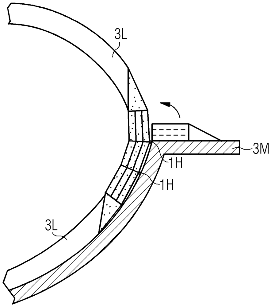
[0040] figure 1 A series of sections through the wind turbine rotor blade 8 is shown, starting from section 81 through the circular root region 80R and progressing to section 85 through the airfoil region. As shown in sections 81-84, the shape of the rotor blades transitions in a complex manner from an initial circular shape. This inner portion of the rotor blade is referred to as the "transition region" or "shoulder region" and must be dimensioned to withstand the high bending moments during normal operation of the wind turbine as well as during high wind conditions. A common approach is to make the rotor blade shell very thick in the transition zone, but the added composite material adds weight to the rotor blade. Alternatively, reinforced structures embedded in lightweight but rigid materials such as wood are known, but these structures are time consuming and expensive to manufacture. In another method like figure 2 As shown in the wireframe representation in , a lightw...


PUM


Abstract

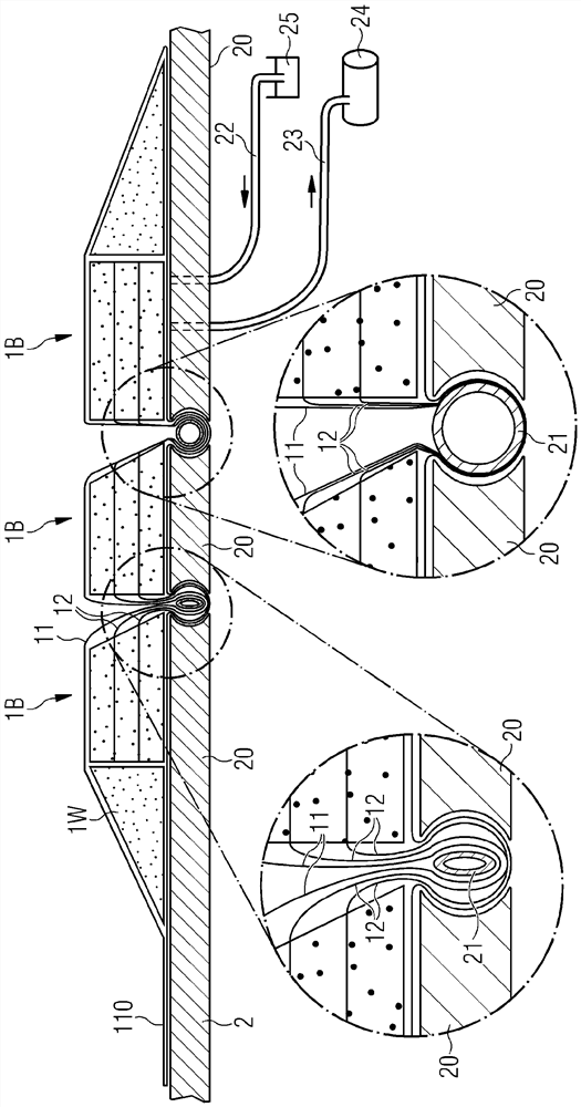
The invention relates to a method of manufacturing an adaptable carbon fiber beam. The invention describes a method of manufacturing an adaptable pre-cast resin-infused carbon fiber beam (1), the method comprising the steps of: arranging a plurality of elongate carbon fiber blocks (1B) side by side; arranging the sheets (11, 12, 13) to enclose the blocks (1B) and to extend on opposite faces of adjacent blocks (1B); arranging the sheets (11, 12, 13) so as to converge into an outwardly projecting elongate bead (1H) at the junction between adjacent blocks (1B); and tensioning the elongated bead (1H) to prevent resin flow between the blocks (1B) during the resin infusion step. The invention further describes a pre-cast adaptable carbon fiber beam (1) made using the method; a method of manufacturing a wind turbine rotor blade (3); and a wind turbine rotor blade (3).

Description

technical field [0001] The present invention describes a method of making an adaptable carbon fiber beam; a precast adaptable carbon fiber beam; a method of making a wind turbine rotor blade; and a wind turbine rotor blade. Background technique [0002] During operation of a wind turbine, rotor blades may experience large bending moments, especially in the inner region. The magnitude of the bending moment increases with increasing rotor blade length, and long rotor blades must be constructed with sufficient stiffness to avoid excessive deformation during normal operation of the wind turbine or during high wind load conditions. [0003] For these reasons, it has become common for wind turbine rotor blade designs to include substantial amounts of glass fiber reinforcement in the inboard regions, especially in the trailing and leading edge regions. It is known to incorporate a sandwich structure with thick fiberglass layers and a core in the inner region of the relatively flat...

Claims


Application Information

Patent Timeline
Patent Type & Authority Applications(China)
IPC IPC(8): B29C70/52B29C70/54
CPCB29C70/523B29C70/525F03D1/0675B29C70/865B29D99/0028B29L2031/085B29C37/0082B29C70/52B29C70/443B29C70/682Y02P70/50Y02E10/72B29C70/84B29K2307/04B29K2309/08B29K2995/0053F05B2230/21F05B2280/2001F05B2280/2006F05B2280/6003
Inventor A.赫鲁普M·尼尔森孙巍
Owner SIEMENS GAMESA RENEWABLE ENERGY AS
Learn More