Mounting structure for power module and vehicle body provided with same

An installation structure and power technology, applied in the direction of electric power unit, connection between superstructure sub-assemblies, power unit, etc., can solve the problems of difficult to install subframe, increased installation cost, large space occupied by power modules, etc. , to ensure available space, improve rolling characteristics, and suppress vibration

Pending Publication Date: 2022-07-08
HYUNDAI MOTOR CO LTD +1
View PDF1 Cites 0 Cited by
  • Summary
  • Abstract
  • Description
  • Claims
  • Application Information

AI Technical Summary

Problems solved by technology

[0006] However, when vehicle development is performed as a vehicle based on a vehicle mounted with a general internal combustion engine and derived from it as an electric vehicle, it may be difficult to install the subframe, or the installation cost may increase significantly
[0007] Therefore, it can be considered to install the power module of the derived electric vehicle on the longitudinal beam, but there may be a problem of separation when the vehicle collides
[0008] In addition, it is conceivable to mount the power module to the upper panel of the vehicle body, but in this case, the distance between the subframes and the center of gravity of the power module is relatively long, resulting in disadvantages in durability and NVH performance
In addition, there is a problem that the space occupied by the power module is relatively large, so that the use space of the front trunk is relatively reduced

Method used


Image

  • Mounting structure for power module and vehicle body provided with same
  • Mounting structure for power module and vehicle body provided with same
  • Mounting structure for power module and vehicle body provided with same

Examples


Embodiment Construction

[0036] Reference will now be made in detail to various specific embodiments of the present invention, examples of which are presented in the accompanying drawings and described below. While the invention will be described in conjunction with exemplary embodiments of the invention, it should be appreciated that this description is not intended to limit the invention to those exemplary embodiments. On the other hand, the invention is intended to cover not only the exemplary embodiments of the invention, but also various alternatives, modifications, Equivalents and other embodiments.

[0037] In the following detailed description, only certain exemplary embodiments of the present invention are shown and described, simply by way of illustration.

[0038] As those skilled in the art would realize, the described embodiments may be modified in various different ways, all without departing from the spirit or scope of the present invention.

[0039] Throughout the specification, part...


PUM


Abstract

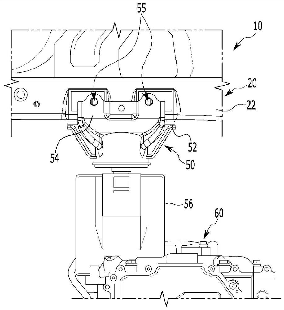
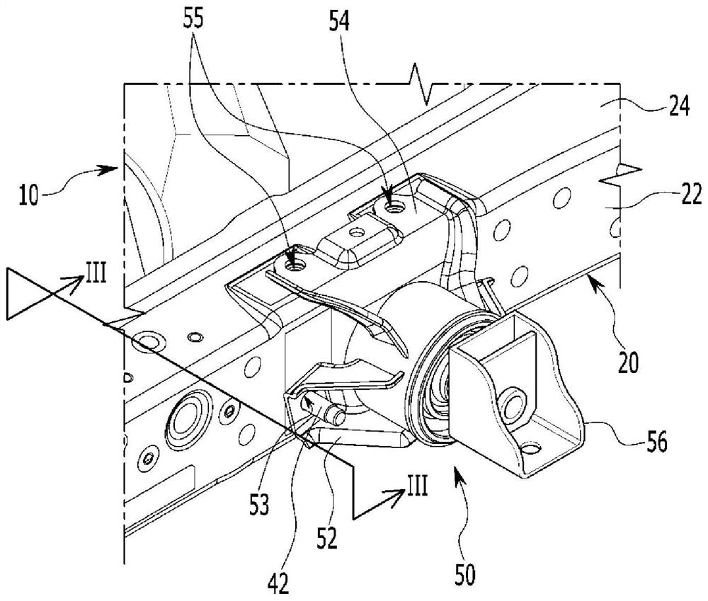
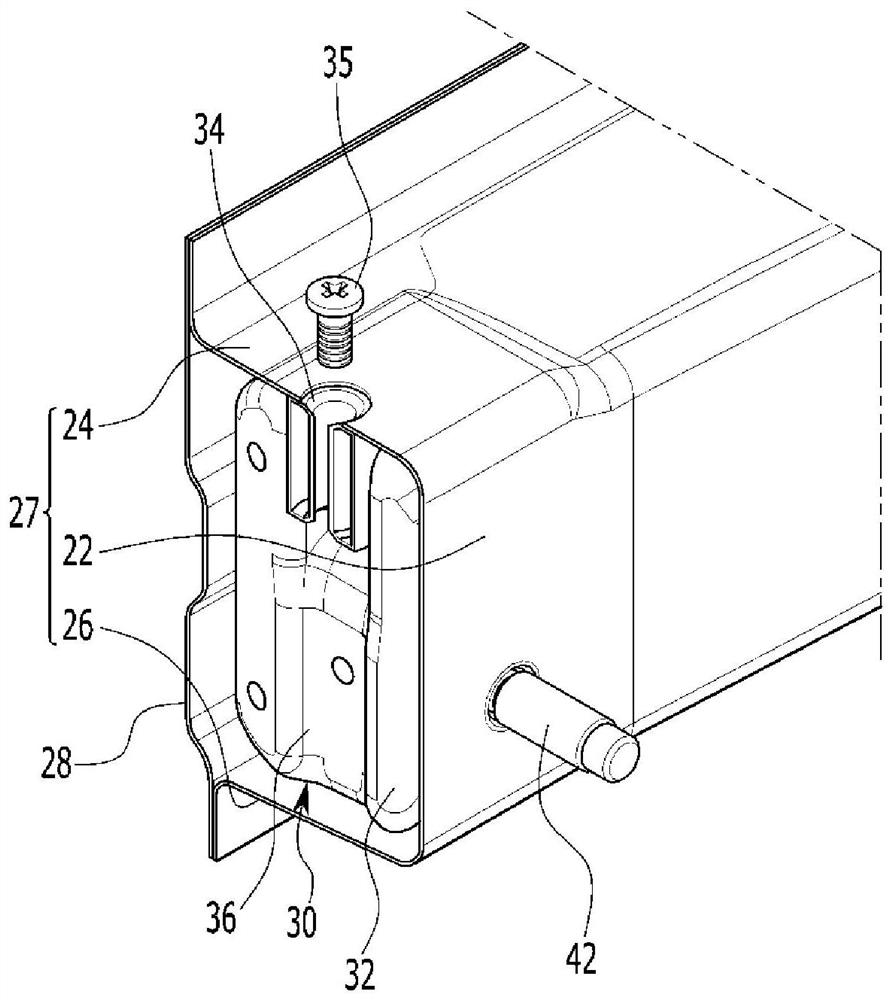
The invention relates to a mounting structure for a power module and a vehicle body provided with the same. The power module mounting structure includes a front side member disposed in a length direction of a vehicle body, the front side member including a side surface formed in an interior direction of the vehicle body and an upper surface connected to the side surface, a bulkhead mounted inside the front side member, and a mounting bracket mounted on the bulkhead, the mounting bracket is connected to a side surface and an upper surface of the front side member through a bulkhead to mount a power module on the mounting bracket.

Description

[0001] CROSS-REFERENCE TO RELATED APPLICATIONS [0002] This application claims priority to and the benefit of Korean Patent Application No. 10-2021-0001394 filed on January 6, 2021, the entire contents of which are incorporated herein for all purposes by this reference. technical field [0003] The present invention relates to a power electric module mounting structure and a vehicle body including the power electric module mounting structure. More particularly, the present invention relates to a power module mounting structure and a vehicle body including the power module mounting structure, which can improve crash and noise, vibration and harshness (NVH) performance and secure a front trunk space. Background technique [0004] Globally, research into electric vehicles (EVs) is accelerating in response to emissions regulations and the need for environmentally friendly vehicles. Here, the electric vehicle may include a battery-powered vehicle and a hydrogen-based fuel cell ...

Claims


Application Information

Patent Timeline
Patent Type & Authority Applications(China)
IPC IPC(8): B60K1/04
CPCB60K1/04B60K2001/0411B60K1/00B60Y2400/202B62D25/08B62D27/023B60K7/0007B60R5/02B60Y2304/01B60Y2306/01B60Y2306/09
Inventor 郑松在
Owner HYUNDAI MOTOR CO LTD
Why Eureka
Try Eureka