Rail-mounted continuous pipe operation machine

A coiled tubing and track-type technology, applied in the direction of drill pipe, casing, drill pipe, etc., can solve the problems of reduced frequency of long-distance transportation, reduced use of chassis vehicles, and long time spent, so as to reduce the complexity of wellhead installation Operational and construction risks, reduced operating costs, and the effect of reduced personnel

Pending Publication Date: 2022-07-08
PETROCHINA CO LTD +3
View PDF0 Cites 0 Cited by
  • Summary
  • Abstract
  • Description
  • Claims
  • Application Information

AI Technical Summary

Problems solved by technology

With the development of more and more platform wells and more operations on the same platform, the frequency of long-distance transportation is greatly reduced, and the utilization rate of chassis vehicles is reduced, resulting in huge waste
On the other hand, the cross-well operation of platform wells requires the traditional method of dismantling the equipment after the operation is com

Method used


Image

  • Rail-mounted continuous pipe operation machine
  • Rail-mounted continuous pipe operation machine
  • Rail-mounted continuous pipe operation machine

Examples


Example Embodiment

[0021] Example 1

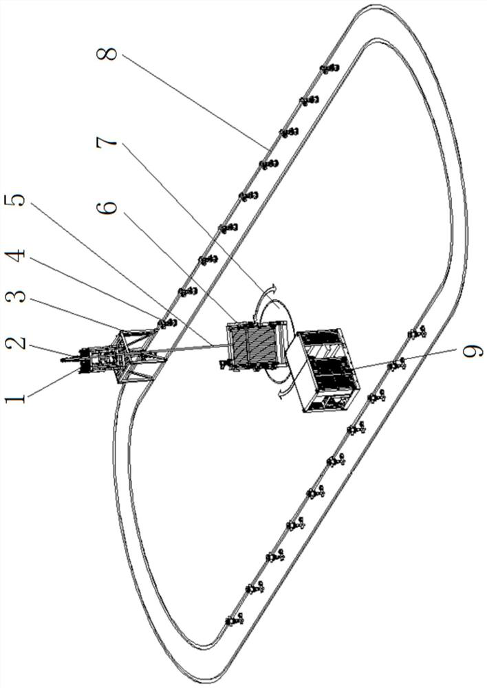
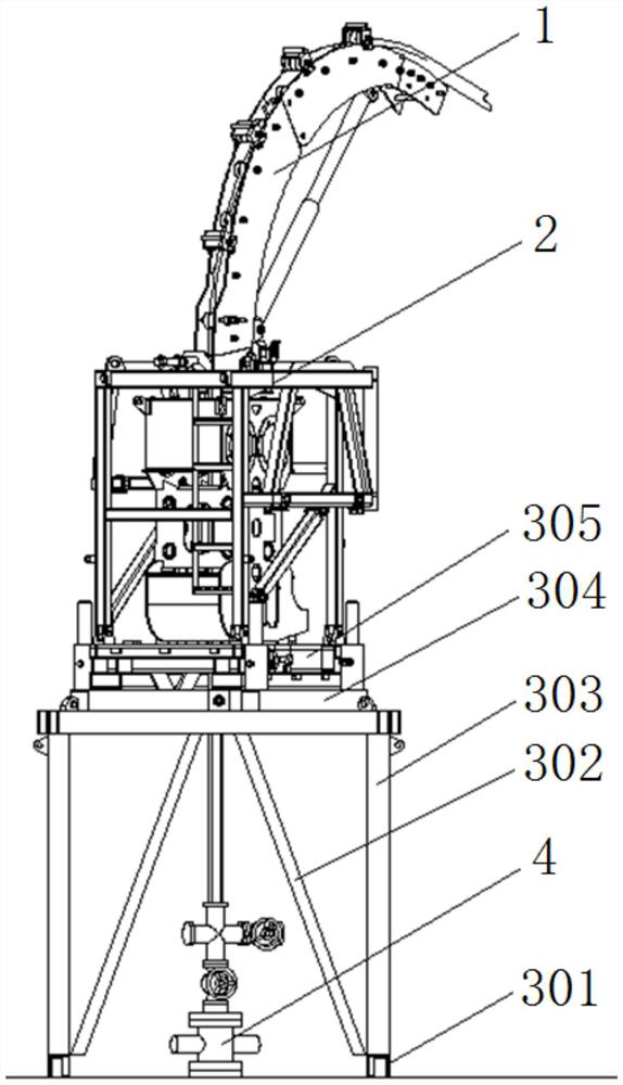
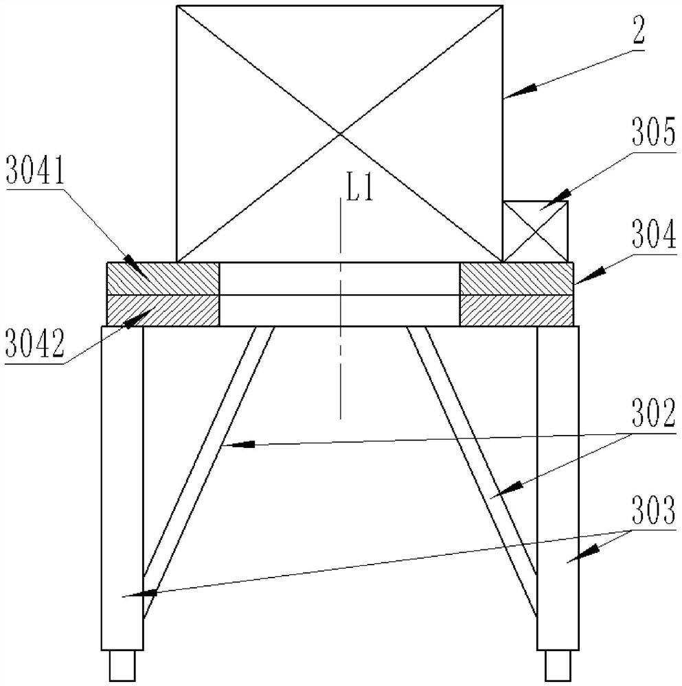
[0022] An orbital coiled tubing machine, comprising a guide 2, an injection head 1, a multifunctional rotating tower 3 and a first track 8 arranged in sequence from top to bottom, the first track 8 extending along the arrangement direction of a row of wellheads 4 , the multifunctional rotating tower 3 can drive the guide 2 and the injection head 1 to walk on the first track 8, and the multifunctional rotating tower 3 can also drive the injection head 1 to rotate around a first straight line, and the first straight line is upright position, such as figure 1 and figure 2 shown.

[0023] In this embodiment, the first track 8 is a double track structure, the first track 8 includes two steel rails that are parallel to each other, and the wellhead 4 is located between the two steel rails. The arrangement of the first rails 8 may depend on the arrangement direction of the wellheads 4 , and the first rails 8 may be arranged in a closed annular structure (such as...

Example Embodiment

[0035] Example 2

[0036]This embodiment is a modification of Embodiment 1. The main difference between this embodiment and Embodiment 1 is that:

[0037] The orbital coiled tubing machine also includes a drum 6, a drum self-propelled platform 10 and a second rail 11 that are sequentially connected from top to bottom. The second rail 11 and the first rail 8 are arranged in a horizontal direction, and the drum self-propelled platform 10 It can drive the roller 6 to walk on the second track 11, and the roller 6 can cooperate with the guide 2 and the injection head 1 to lift the continuous pipe 5, such as Figure 4 shown.

[0038] This embodiment does not contain the rotating platform 7 in the first embodiment, and the rotating platform 7 in the first embodiment is replaced by the roller self-propelled platform 10 and the second rail 11 in this embodiment. The second rail 11 and the first rail 8 may be arranged in parallel, and the second rail 11 and the first rail 8 may also b...


PUM


Abstract

The invention provides a rail type continuous pipe operation machine which comprises a guider (2), an injection head (1), a multifunctional rotating tower (3) and a first rail (8) which are sequentially arranged from top to bottom, the first rail (8) extends in the arrangement direction of well mouths (4), and the multifunctional rotating tower (3) can drive the guider (2) and the injection head (1) to walk on the first rail (8). The multifunctional rotating tower (3) can further drive the injection head (1) to rotate around a first straight line, and the first straight line is in an upright state. According to the rail type continuous pipe operation machine, well rotating movement of well mouth equipment can be conducted through the rails, movement and direction adjustment of the rollers or synchronous movement of the double rails can be conducted through the rails and the rotating platform, supporting and installation positioning of the well mouth equipment are achieved through the multifunctional rotating tower, and rapid cross-well installation of the continuous pipe operation equipment is guaranteed; operation efficiency is improved, personnel are reduced, and cost is reduced.

Description

technical field [0001] The invention relates to the field of petroleum exploitation equipment, in particular to an orbital coiled pipe working machine. Background technique [0002] Coiled tubing technology has gradually developed into an indispensable petroleum engineering service technology in the field of petroleum engineering, and is widely used in drilling, workover, stimulation, logging and other operations. The development of coiled tubing equipment has formed three categories: truck-mounted, skid-mounted, and tow-mounted. Equipment transfer is completed by chassis vehicles, and equipment support during operation is mainly implemented by cranes. With the development of more and more platform wells and the increase of operations on the same platform, the frequency of long-distance transportation is greatly reduced, and the utilization rate of chassis vehicles is reduced, resulting in huge waste. On the other hand, the traditional method of cross-well operation in plat...

Claims


Application Information

Patent Timeline
IPC IPC(8): E21B19/22
CPCE21B19/22
Inventor 杨高马青胡志强周忠城袁文才刘平国颜家福康凯柳庆仁殷卓成
Owner PETROCHINA CO LTD
Why Eureka
Try Eureka