Online intelligent detection equipment for computer mainboard
A computer motherboard, intelligent detection technology, applied in electronic circuit testing, measuring device casing, comprehensive factory control, etc., can solve the problems of high operation intensity, low detection efficiency, inconvenient classification of defective and genuine products, etc., to achieve high detection efficiency , The effect of low operation intensity and continuous detection
- Summary
- Abstract
- Description
- Claims
- Application Information
AI Technical Summary
Problems solved by technology
Method used
Image
Examples
Embodiment 1
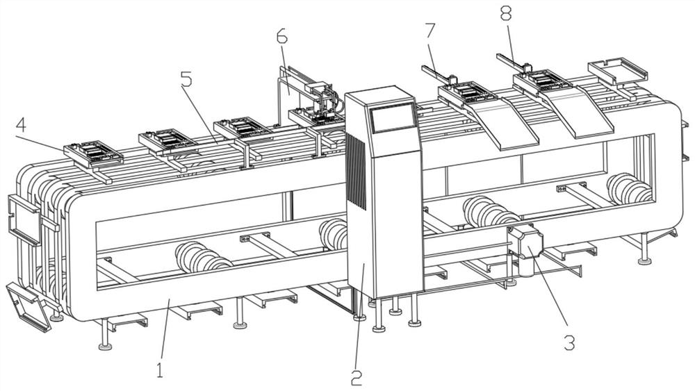
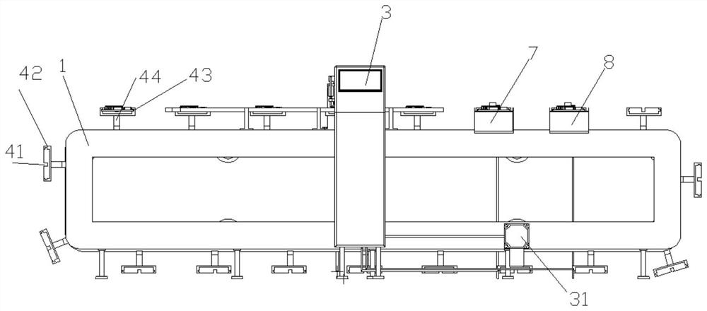
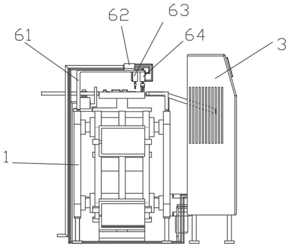
[0048] like figure 1 , 2 , 3, 4, 5, 6 and 8, a computer motherboard online intelligent detection equipment, including a rack 1 and a control machine 2, the inner wall of the rack 1 is connected with an equidistant drive assembly 3 for intermittent movement of the computer motherboard;
[0049] The equidistant drive assembly 3 includes a servo motor 31, a synchronous belt 32, a rotating roller 33 and a synchronizing wheel 34. The inner wall of the frame 1 rotates a rotating roller 33 through a bearing, and the rotating roller 33 is fixed with a synchronizing wheel 34 at equal intervals, and the synchronizing wheels 34 rotate respectively. There is a timing belt 32, the servo motor 31 is installed on the side wall of the frame 1, the output end of the servo motor 31 is fixed coaxially with one end of one of the rotating rollers 33, and the servo motor 31 rotates one circle to drive the distance that the timing belt 32 moves. is the distance between the adjacent motherboard plug...
Embodiment 2
[0058] Example 2 is a further improvement to Example 1.
[0059] like figure 1 , 4 As shown in and 6, the card position structure 5 includes an arc guide plate 51, a card position plate 52 and a connecting seat 53. The connecting seat 53 is installed on the rack 1 to move, and a card position plate 52 is fixed on the top of the connecting seat 53. The end of 52 is fixed with an arc guide plate 51. After the computer motherboard is installed on the motherboard plug-in assembly 4, it first contacts the arc guide plate 51 and then contacts the card position plate 52. After the computer motherboard contacts the card position plate 52, the card position plate 52 is in contact. Limit the computer motherboard in the motherboard plug-in assembly 4 .
[0060] When the motherboard plug-in assembly 4 moves to the arc-shaped guide plate 51 of the locking structure 5, the arc-shaped guide plate 51 pushes the computer motherboard in the motherboard plug-in assembly 4 into the support base...
Embodiment 3
[0062] Embodiment 3 is a further improvement of Embodiment 2.
[0063] like figure 1 , 2 , 5 and 7, the defective product discharge assembly 7 includes a guide plate 71, a mounting seat 72, a servo motor 73, a straight plate 74, a sliding groove 75, a sliding plate 76, a gear ring 77 and a slot 78. The ends are in contact with the 4 side walls, the guide plate 71 is fixedly installed on one side of the top of the rack 1, the mounting seat 72 is fixed on the other side of the top of the rack 1, the top of the mounting seat 72 is fixed with a servo motor 73 and a straight plate 74, the straight plate 74 is arranged close to the synchronous belt 32, the output end of the servo motor 73 is coaxially fixed with a gear ring 77, the straight plate 74 is provided with a sliding groove 75, the inner wall of the sliding groove 75 is fitted and slidably connected with a sliding plate 76, and the sliding plate 76 is provided with a matching use with the ring gear 77 The slot 78 is forme...
PUM
 Abstract
Description
Claims
Application Information
 - R&D
- Intellectual Property
- Life Sciences
- Materials
- Tech Scout
- Unparalleled Data Quality
- Higher Quality Content
- 60% Fewer Hallucinations
Browse by: Latest US Patents, China's latest patents, Technical Efficacy Thesaurus, Application Domain, Technology Topic, Popular Technical Reports.
© 2025 PatSnap. All rights reserved.Legal|Privacy policy|Modern Slavery Act Transparency Statement|Sitemap|About US| Contact US: help@patsnap.com


